
Carbon Fiber Material Selection Guide for Engineering Applications
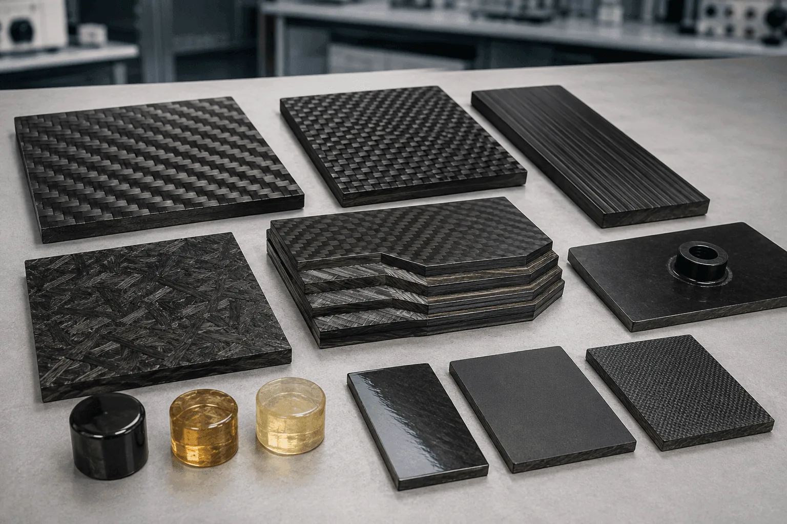
Selecting carbon fiber is not simply a choice between T300, T700, 3K fabric or a glossy finish. The finished component depends on the fiber grade, reinforcement format, fiber direction, resin system, laminate design, geometry and manufacturing process working together.
This carbon fiber material selection guide helps engineers and OEM buyers organize those decisions before requesting a tube, rod, sheet or custom CFRP component.
Grade & Modulus · Weave & Tow · Layup Direction · Resin & Process
Final material and laminate requirements should be confirmed against the actual loads, environment, interfaces and acceptance criteria of the application.
Start with Loads
Identify bending, axial, torsional, impact and fatigue demands before choosing a material.
Separate Strength from Stiffness
A higher tensile strength does not automatically mean a higher modulus or a better component.
Design the Laminate
Fiber orientation and ply balance often influence performance more than the visible weave.
Match the Process
Geometry, tooling, quantity, finish and tolerance determine which manufacturing route is practical.
How to Choose the Right Carbon Fiber Material
A useful material specification begins with the component requirements, not with a familiar fiber name. Work through the following sequence and document the assumptions that affect the design.
01 · Define the Load
Map load direction, magnitude, support points and likely combinations of bending, tension, compression, shear and torsion.
02 · Set Performance Targets
Define stiffness, strength, mass, deflection, impact, fatigue and dimensional-stability requirements.
03 · Review the Environment
Record temperature, moisture, UV, chemicals, electrical contact, fire requirements and outdoor exposure.
04 · Choose the Product Form
Decide whether the design is best served by a tube, rod, sheet, constant profile or molded component.
05 · Select Fiber Architecture
Choose UD, woven, braided or combined reinforcement and place fibers along the important load paths.
06 · Match Resin and Process
Confirm that the resin, cure route, tooling and manufacturing volume are compatible.
07 · Define Interfaces
Review holes, fasteners, inserts, bonded joints, edge distances and assembly contact with metals.
08 · Validate the Component
Use drawings, calculations, prototypes, coupons or component testing appropriate to the project risk.
Carbon Fiber Selection at a Glance
Use this table as a screening tool. It is not a final laminate specification and does not replace application-specific engineering review.
| Primary Requirement | Material Direction to Review | Do Not Ignore |
|---|---|---|
| Axial stiffness | Higher 0° or UD contribution | Buckling, joints and transverse stability |
| Torsional performance | Balanced ±45° reinforcement | End fittings and local load transfer |
| Multi-directional loading | Balanced or quasi-isotropic laminate | Weight, ply count and real load dominance |
| Complex curved geometry | Drapable fabric or suitable prepreg | Wrinkling, bridging, radii and trim lines |
| Cosmetic surface | Controlled twill, plain or spread-tow face ply | The visible ply does not define the internal structure |
| Temperature or chemicals | Application-matched resin system | Cure, Tg, duration, moisture and test conditions |
Carbon Fiber Grades: Strength Is Not the Same as Stiffness
Carbon fibers are commonly grouped into standard-, intermediate- and high-modulus families. Tensile strength describes the stress at failure in a specified test, while tensile modulus describes resistance to elastic strain. A fiber can provide higher tensile strength without a proportional increase in modulus.
T300 and T700S are both commonly treated as standard-modulus fibers, even though T700S provides higher typical tensile strength. Intermediate- and high-modulus fibers may improve stiffness-driven designs, but cost, strain capability, processing, supply and damage sensitivity must also be reviewed.
Standard Modulus
A practical baseline for many industrial structures and cost-sensitive applications.
Intermediate Modulus
Consider when stiffness-to-weight is important and the full laminate justifies the upgrade.
High Modulus
Used for stiffness-critical designs after strain, handling, cost and availability are evaluated.
High Strength
Useful when allowable strength is important, but it should not be confused with high modulus.
Specification rule: compare the exact supplier grade and datasheet. Do not convert a fiber value directly into a guaranteed property for the finished laminate or component.
Unidirectional, Plain Weave, Twill or Forged Carbon?
The reinforcement format affects fiber direction, drapability, surface appearance, handling and the manufacturing process. The face pattern alone does not reveal the full laminate beneath it.
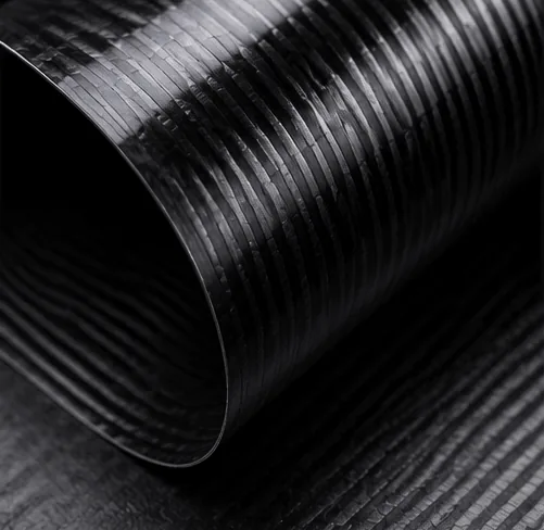
Unidirectional Carbon Fiber
Fibers are concentrated in one direction. UD reinforcement is efficient for directional stiffness and strength when the principal load path is known, but transverse and shear requirements normally need additional orientations.
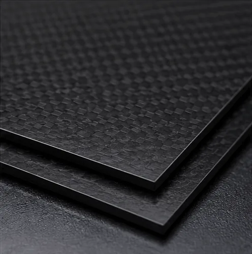
Plain Weave Carbon Fiber
Plain weave interlaces each tow frequently, helping fabric stability and balanced 0°/90° reinforcement. Drapability and the visual pattern differ from twill, so complex contours must be reviewed.
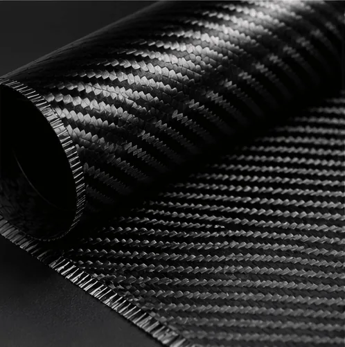
2×2 Twill Carbon Fiber
Twill is widely used for its recognizable diagonal appearance and useful drapability. It can form a cosmetic surface while internal UD or other orientations provide the structural load paths.
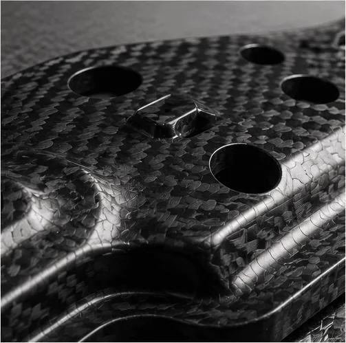
Forged Carbon Appearance
Chopped-fiber molding can create a nonwoven, marbled appearance and suit selected molded geometries. Performance depends on fiber length, distribution, resin, compaction and process control.
Do not use 3K, 6K or 12K as a quality ranking. The K-count identifies the approximate number of filaments in a tow. Fiber grade, weave, areal weight, fiber volume, resin and laminate quality still need to be specified.
How Layup Direction Changes CFRP Performance
Carbon fiber is anisotropic: the laminate response changes with fiber direction. A good selection guide must connect each ply orientation to the real load path rather than treating laminate thickness as the only design variable.
0° · Axial Direction
Usually contributes strongly to axial stiffness and bending performance when aligned with the main structural direction.
90° · Transverse or Hoop
Supports transverse stability, circumference loads and resistance to local shape change in tubes.
+45° / −45° · Shear
Balanced off-axis plies are commonly used to carry shear and improve torsional response.
Balanced Multi-Angle Layup
Combines orientations for multi-directional service while controlling coupling and laminate behavior.
A tube designed mainly for bending, a drive shaft dominated by torsion and a flat mounting plate with loads in several directions should not receive the same layup. Holes, cutouts and bonded fittings may also require local reinforcement.
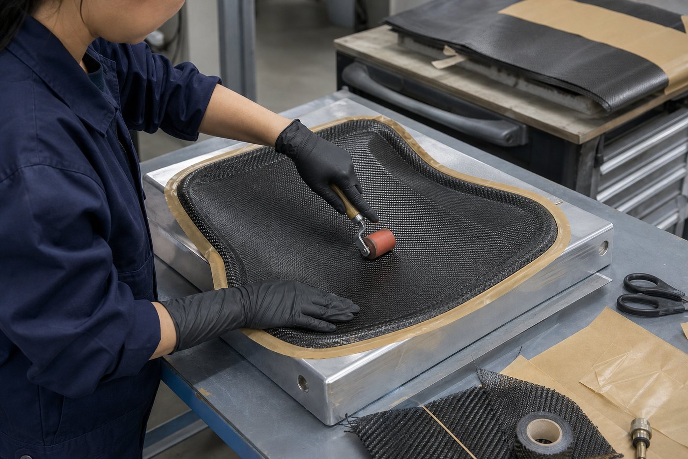
Select the Resin System with the Application
The matrix holds the reinforcement, transfers load between fibers, protects the laminate and determines much of the processing window and environmental response. Resin selection should be coordinated with the reinforcement format and manufacturing route.
Temperature
Review cure temperature, glass-transition behavior, continuous exposure and short-duration peaks.
Moisture & Chemicals
Define fluids, concentration, duration, cleaning agents and immersion or splash conditions.
Outdoor Exposure
Consider UV protection, coating, moisture cycling and the required appearance life.
Bonding & Finish
Confirm surface preparation, adhesive compatibility, coating and cosmetic requirements.
Do not specify a universal service temperature from the word “epoxy.” Use the actual resin-system data and validate the finished process when the environment is critical.
Choose Carbon Fiber by Component Geometry
Product form determines how fibers can be placed, which tolerances are practical and how the component will connect to the rest of the assembly.
Carbon Fiber Tubes
Review bending, torsion, crushing, wall thickness, profile shape, tube process and end connections.
Carbon Fiber Rods
Useful for axial members and constant cross sections; review diameter, straightness, end machining and bonded interfaces.
Carbon Fiber Sheets
Suitable for panels, brackets and CNC-cut parts; choose thickness, surface, layup and machining criteria.
Custom CFRP Parts
Curved or integrated geometry may require tooling, prepreg or molding, trim development and local interface design.
Match the Carbon Fiber Material to the Manufacturing Route
Material availability alone does not make a process suitable. Geometry, fiber path, surface class, tooling investment, batch size and inspection requirements must be evaluated together.
| Manufacturing Route | Best Starting Point | Selection Questions |
|---|---|---|
| Pultrusion | Constant-section rods and profiles | Axial performance, transverse stability, profile and production length |
| Roll Wrapping | Tubes with engineered ply schedules | Mandrel, taper, wall, finish, bending and torsion |
| Filament Winding | Rotational components and hoop-dominated structures | Winding angle, closed geometry, ports and pressure requirements |
| Prepreg Layup / Molding | Controlled laminates and complex molded parts | Tooling, cure equipment, ply placement, trim and quantity |
| Vacuum Bagging / Infusion | Selected shells, panels and low-volume parts | Permeability, resin flow, compaction, surface and repeatability |
| CNC Machining | Finished sheet parts and secondary features | Laminate, workholding, dust control, edge distance and tolerance |
Carbon Fiber Material Selection Mistakes to Avoid
Choosing by Appearance
A perfect twill surface does not prove the internal fiber directions, fiber grade or laminate quality.
Treating 3K as a Grade
Tow count describes filament quantity, not a complete strength, modulus or quality specification.
Assuming Higher Modulus Is Better
Greater stiffness may add cost or reduce design margin in areas where strain and impact matter.
Ignoring Fiber Direction
Thickness alone cannot correct a laminate that places too little reinforcement along the important load path.
Using Fiber Data as Part Data
Finished performance also depends on resin, fiber volume, voids, cure, geometry, machining and joints.
Copying an Unnecessary Grade
An aerospace designation may increase cost and lead time without improving an industrial component.
Forgetting the Joint
Fasteners, bonded inserts, edges and cutouts can control failure before the main laminate reaches its limit.
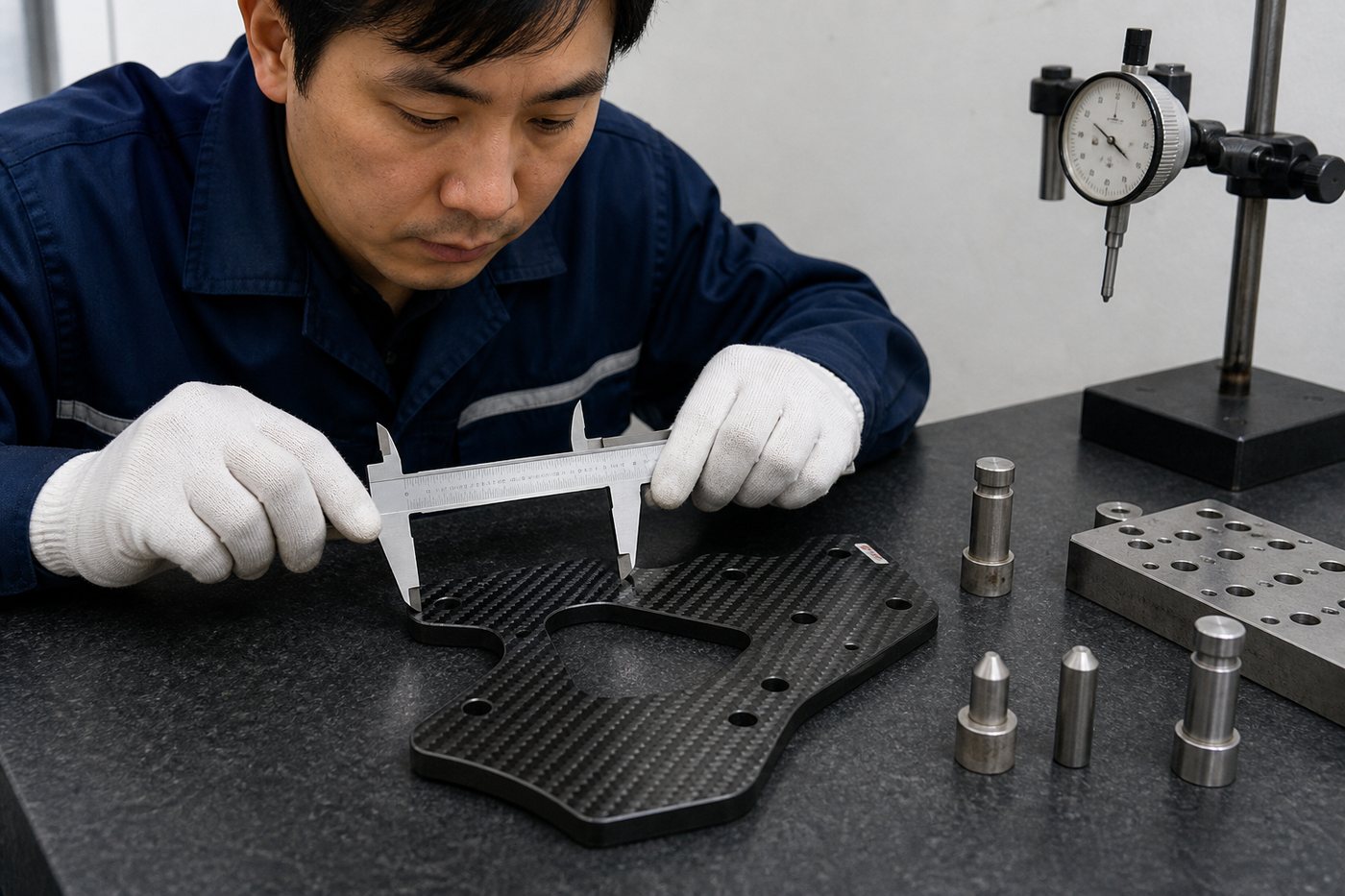
Skipping Validation
Critical components require an agreed calculation, prototype, coupon or component-test strategy.
Information Needed for Carbon Fiber Material Selection
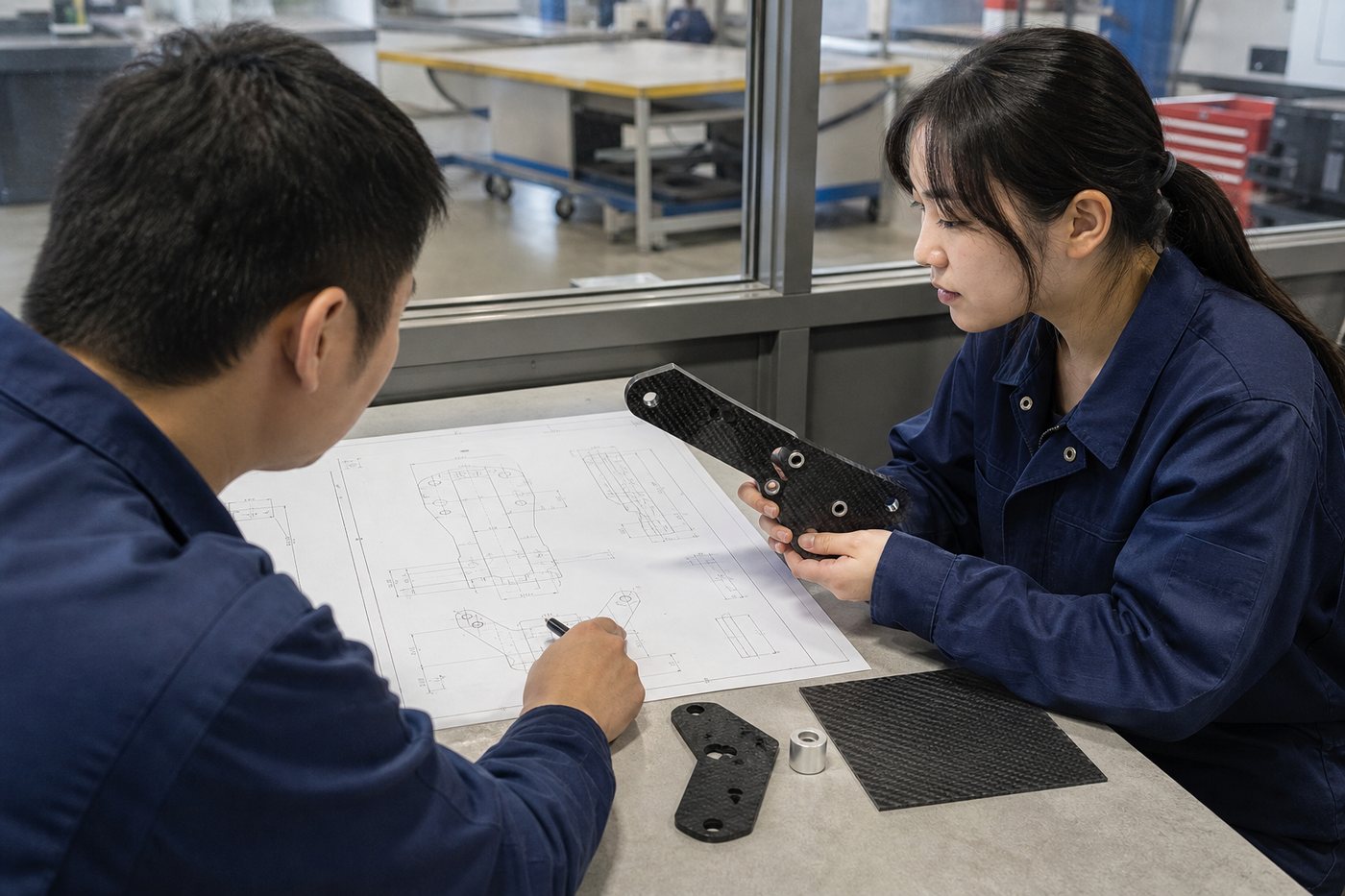
Better input produces a more useful material and process recommendation. Send available information even when the design is still being developed.
Geometry
2D drawing, 3D CAD, dimensions, wall or thickness and assembly envelope.
Loads
Directions, magnitudes, duty cycle, impact, fatigue, safety factors and deflection target.
Environment
Temperature, moisture, UV, chemicals, electrical contact and fire requirements.
Interfaces
Holes, inserts, fasteners, bonded joints, bearings, metal contact and edge distances.
Production
Prototype quantity, annual demand, tooling budget and target delivery schedule.
Acceptance
Critical tolerances, surface class, inspection, documentation and testing needs.
Carbon Fiber Material Selection FAQ
Common questions from engineers and buyers preparing a carbon fiber component specification.
Start with loads, stiffness, environment, geometry, interfaces, quantity and validation requirements. Then select the fiber grade, reinforcement format, layup, resin and manufacturing process as one system.
T700S offers higher typical tensile strength than T300 while both are commonly classified as standard-modulus fibers. The better choice depends on the laminate, load case, cost, supply and required validation.
Strength relates to the stress at failure in a defined test. Modulus describes elastic stiffness. A stronger fiber is not automatically much stiffer.
K-count indicates the approximate number of filaments in a tow. It does not by itself determine strength or quality. Compare the fiber grade, fabric construction, resin and finished laminate.
UD reinforcement is efficient in a known principal direction. Woven fabric provides fibers in multiple directions and may improve handling or appearance. Many structural laminates combine both.
Balanced off-axis reinforcement, often involving +45° and -45° plies, commonly contributes to torsional performance. The complete geometry, joints and other loads must still be reviewed.
The resin transfers load, protects fibers and influences cure, temperature, moisture, chemicals, toughness, finish and bonding. Use the exact resin-system data for critical conditions.
Carbosources can review the drawing, loads, environment, quantity, interfaces and inspection needs to propose a practical material and manufacturing direction for quotation.
Carbon Fiber Products and Engineering Resources
Carbon Fiber Tubes
Compare round, square, hexagonal, pultruded and roll-wrapped tube options.
Carbon Fiber Rods
Review solid rods, square profiles and threaded interface solutions.
Carbon Fiber Sheets
Explore UD, flexible, colored and structural sheet formats.
Custom Carbon Fiber Parts
Move from material selection to drawing review, processing and OEM production.
Request Carbon Fiber Material Selection Support
Send your drawing, loads, environment, interfaces, quantity and acceptance requirements. Carbosources will review the product form, material direction and manufacturing route for quotation.