
Home › Technical Support
Carbon Fiber Engineering and Technical Support
Practical support for carbon fiber material selection, drawing review, design for manufacturability, process planning, prototypes, CNC machining, bonded interfaces and repeat OEM production.
Send your application requirements, drawing or CAD file. Carbosources will review the information that affects material, geometry, tooling, manufacturing, inspection and quotation.
Drawing Review · Material & Layup · DFM · Prototype Support
Technical review is based on the information supplied for the specific project. Final structural validation and regulated approvals must be defined separately.
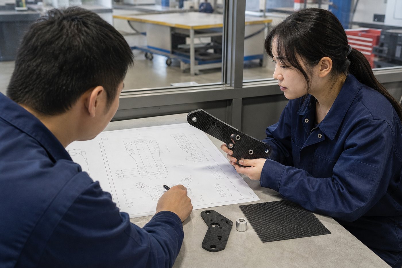
Technical Support for Custom Carbon Fiber Projects
Support is organized around decisions that help turn an application requirement into a buildable, inspectable and commercially realistic CFRP component.
Concept & Feasibility
Review the application, loads, geometry, interfaces, quantity and whether CFRP is a practical direction.
Drawing & CAD Review
Identify features that affect layup, tooling, machining, assembly, tolerance and inspection.
Material & Process Selection
Connect fiber grade, architecture, resin, product form and production route to the requirement.
Prototype to Production
Plan samples, approval criteria, revision control and the move into repeat OEM supply.
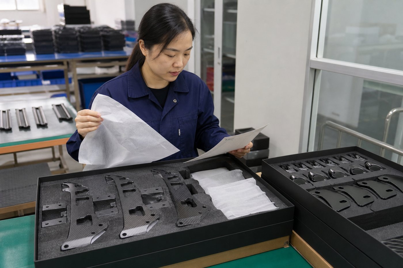
Information Required for a Technical Review
Complete information produces a more useful review and quotation. Send what is available and identify assumptions that still need to be confirmed.
Geometry
2D drawing, 3D CAD, dimensions, wall or thickness and assembly envelope.
Performance
Load directions, stiffness or deflection target, impact, fatigue and weight target.
Environment
Temperature, moisture, UV, chemicals, electrical contact and regulatory conditions.
Interfaces
Holes, fasteners, inserts, bonded joints, bearings, datums and adjacent materials.
Production
Prototype quantity, annual demand, tooling budget and target schedule.
Acceptance
Critical tolerances, surface class, inspection, testing and documentation needs.
Carbon Fiber Drawing and Manufacturability Review
A geometry created for aluminum or plastic is not always ready for carbon fiber production. CFRP carries load through controlled fiber directions, so radii, holes, cutouts, thickness transitions and joints must be reviewed with the laminate and manufacturing process.
The objective is not to redesign the product without approval. It is to identify features that may increase risk, tooling complexity, machining time or inspection difficulty before production begins.
| Design Feature | Technical Review | Why It Matters |
|---|---|---|
| Sharp corners | Radius, ply drape and tool access | Wrinkling, bridging and stress concentration |
| Holes near an edge | Edge distance, local reinforcement and machining | Fiber interruption and fastener load transfer |
| Thin walls | Layup, compaction and local stability | Process repeatability and buckling risk |
| Metal inserts | Bond area, insert geometry and isolation | Load transfer, temperature and galvanic exposure |
| Tight tolerances | Datum, molding capability and secondary machining | Inspection method and manufacturing cost |
| Cosmetic surface | Tool face, fabric, coating and trim line | Visual acceptance and repeatability |
Carbon Fiber Material and Layup Selection Support
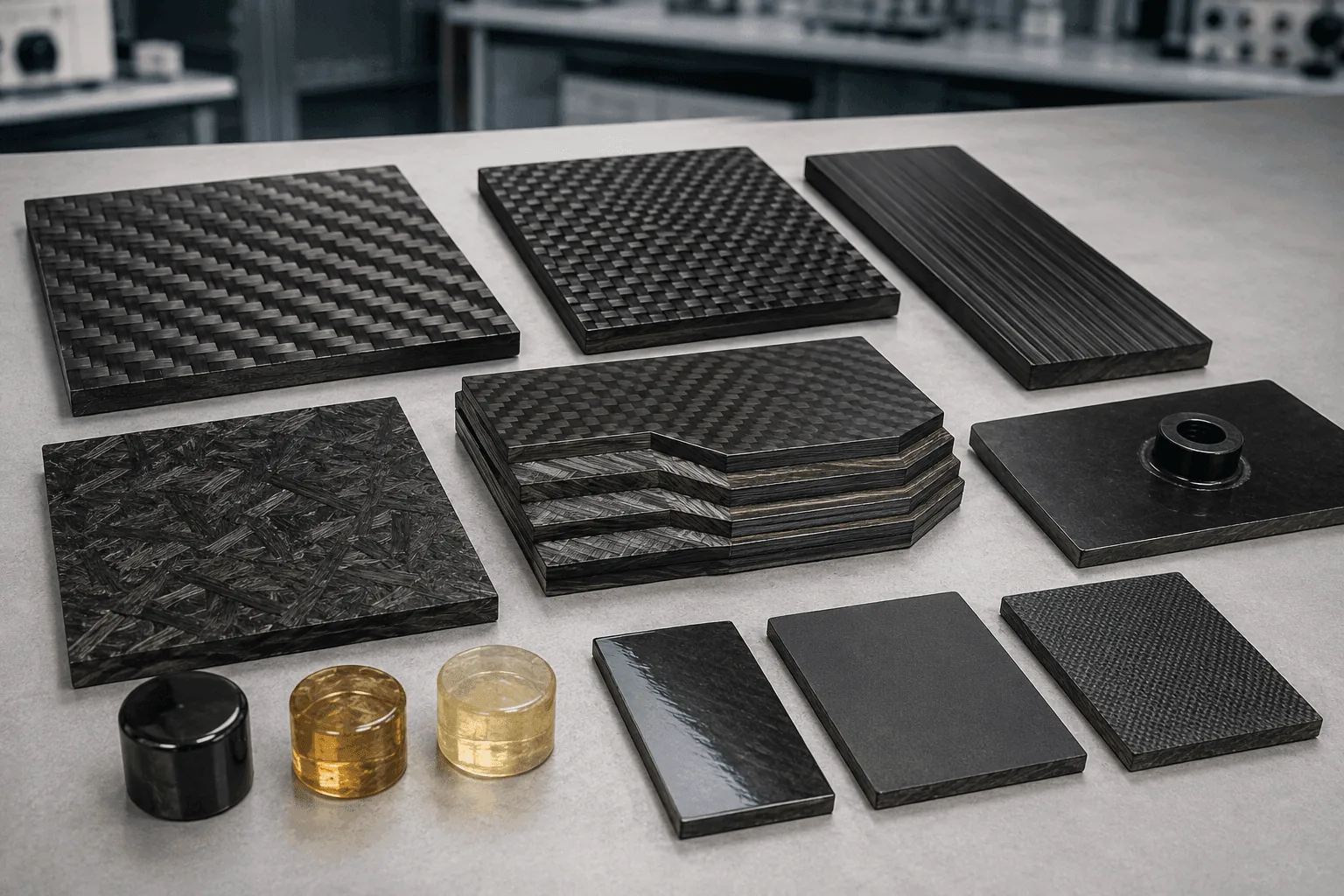
Material selection covers more than a familiar grade name or visible weave. The review connects the fiber family, reinforcement format, ply orientation, resin system and product form to the load path and service environment.
Fiber Grade
Compare standard-, intermediate- or high-modulus directions against strength, strain, cost and supply.
Reinforcement
Review UD, woven, braided or combined architecture around geometry and loads.
Ply Orientation
Place 0°, 90° and off-axis reinforcement according to bending, transverse and torsional demands.
Resin & Environment
Match cure, temperature, moisture, chemicals, finish and bonding requirements.
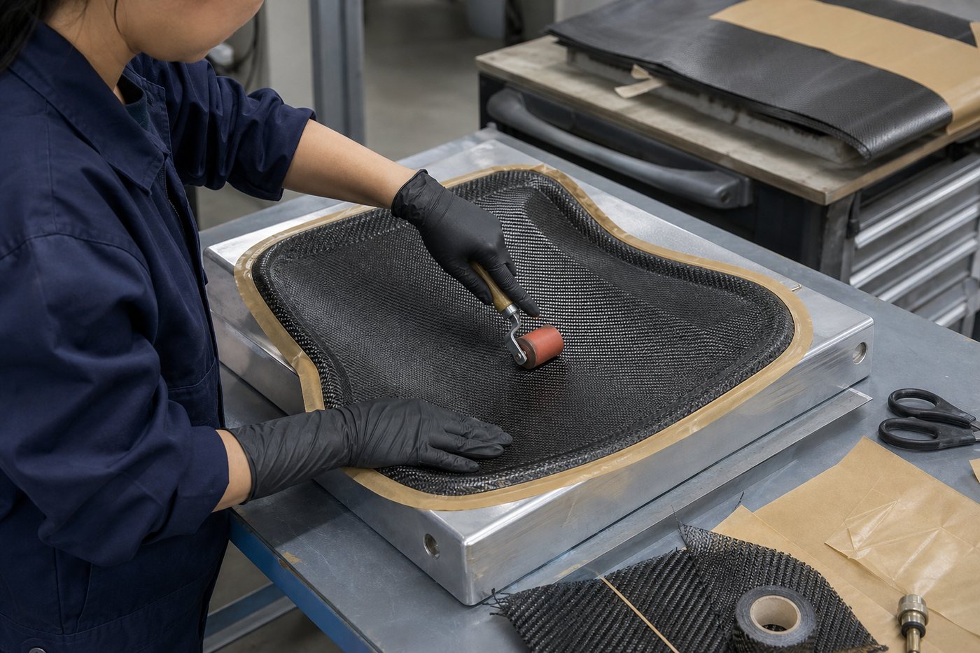
Select a Practical Carbon Fiber Manufacturing Process
The process should be selected after reviewing geometry, fiber path, surface class, tooling, quantity, tolerance and inspection. A process chosen too early can force unnecessary design compromises or cost.
| Component Direction | Process to Review | Key Inputs |
|---|---|---|
| Solid rod or constant profile | Pultrusion | Section, axial load, length and volume |
| Round or profiled tube | Roll wrapping, pultrusion or suitable tube route | Diameter, wall, layup, finish and end features |
| Flat plate or bracket | Sheet laminate and CNC machining | Thickness, fiber direction, contour and holes |
| Curved shell or cover | Prepreg or project-specific molding | Tooling, radii, ply drape, trim and surface |
| Part with metal interfaces | Machining, bonding and inserts | Load transfer, bond area, environment and inspection |
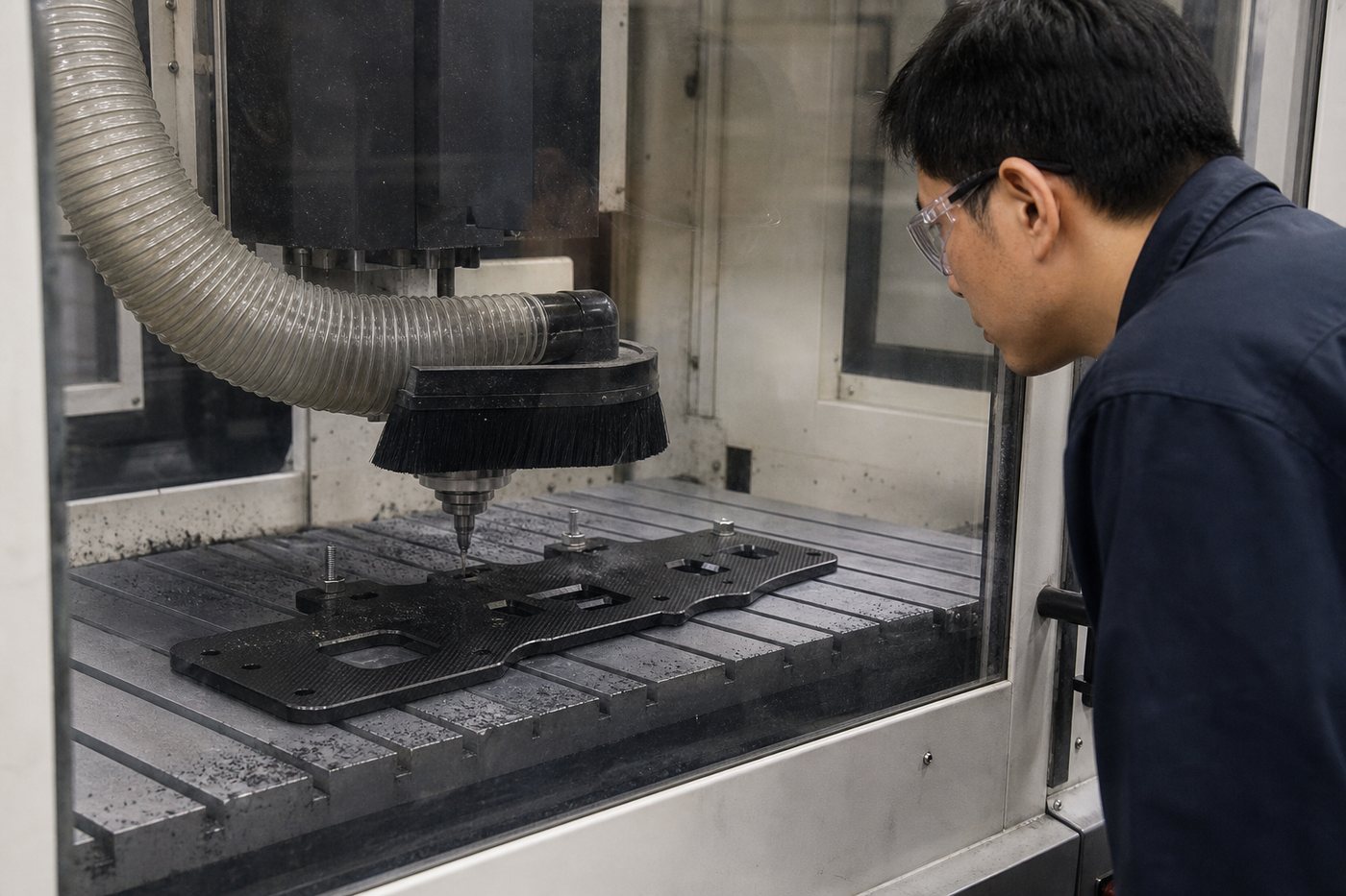
CNC Machining and Joint Design Support
Carbon fiber machining and assembly should be planned with the laminate. Holes and cutouts interrupt fibers, while bonded interfaces transfer load through surface preparation, adhesive geometry and the surrounding composite.
CNC Features
Cutting, drilling, slots, pockets, countersinks, trimming and edge finishing.
Machining Review
Tool access, workholding, edge distance, breakout, dust control and tolerance.
Bonded Interfaces
Bond area, adhesive, surface preparation, joint geometry and inspection.
Metal Contact
Insert material, isolation, moisture and galvanic-corrosion considerations.
Technical Review for Carbon-to-Metal Interfaces
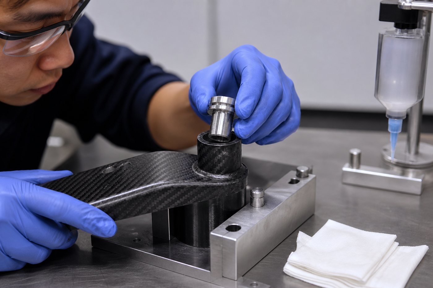
Threaded inserts, bushings and bonded fittings can simplify final assembly, but the connection may govern component performance. Technical review considers the insert geometry, adhesive area, load direction, bond-line control, temperature, moisture and adjacent materials.
Functional pull, torque or proof testing is included only when the method, load, sampling and acceptance criteria are agreed for the project.
From Feasibility Review to Repeat OEM Production
Technical support changes as the project moves from an early requirement to an approved production specification.
01 · Requirements
Collect the drawing, application, loads, environment, quantity and acceptance needs.
02 · Feasibility
Review product form, geometry, material direction, process and major commercial constraints.
03 · DFM Feedback
Identify drawing features, interfaces, tooling and inspection points that need clarification.
04 · Prototype Plan
Confirm material, process, setup, sample quantity and evaluation criteria.
05 · Manufacture
Produce the prototype or first article using the agreed technical assumptions.
06 · Inspection
Check critical dimensions, surface, interfaces and documented acceptance criteria.
07 · Approval
Freeze the drawing revision, process scope and changes required before production.
08 · Repeat Supply
Control revisions, batch production, inspection, identification and packaging.
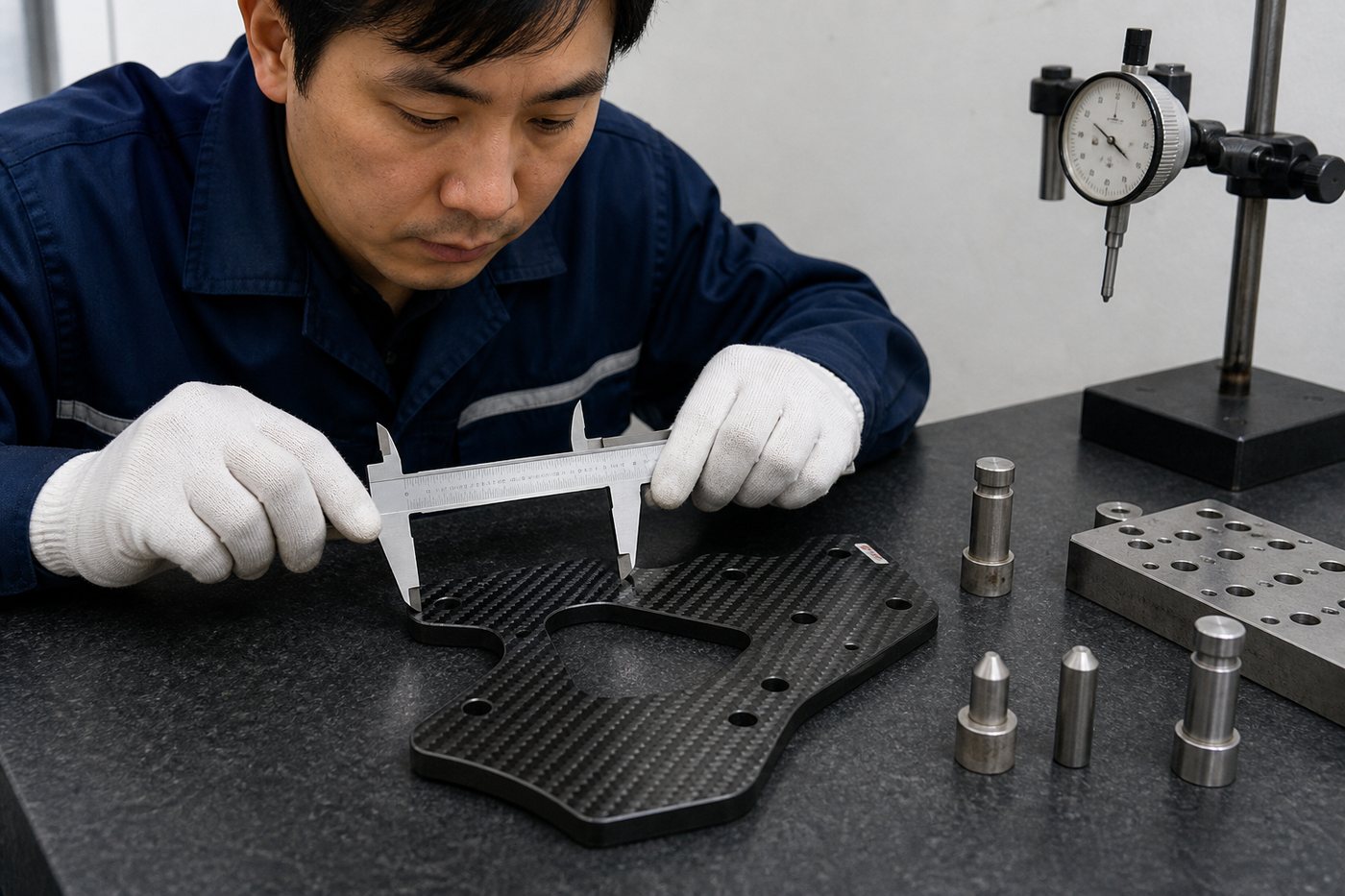
Prototype Inspection and Production Readiness
A prototype should confirm more than appearance. The project team can define the dimensions, interfaces, surface criteria and functional checks needed before repeat production.
Dimensional Review
Datums, critical dimensions, holes and assembly interfaces.
Surface Acceptance
Finish, weave alignment, trim and permitted visual variation.
Fit & Interface
Insert position, hardware, mating parts and assembly clearance.
Production Release
Approved revision, process assumptions, inspection and packaging.
Quality Planning for Repeat Carbon Fiber Production
Moving from a successful sample to repeat supply requires a controlled drawing, clear acceptance criteria and a practical inspection plan. The project scope can define first-article review, critical dimensions, surface criteria, insert checks, batch records, identification and packaging.
Testing and certification are provided only when the method, standard, sample plan and acceptance limits are included in the agreed scope.
Revision Control
Use the approved drawing and record technical changes before production.
Critical Characteristics
Identify dimensions and interfaces that directly affect fit or function.
Inspection Planning
Match tools, fixtures, sampling and records to product risk and quantity.
Packing & Identification
Protect surfaces, long profiles, interfaces and batch identification.
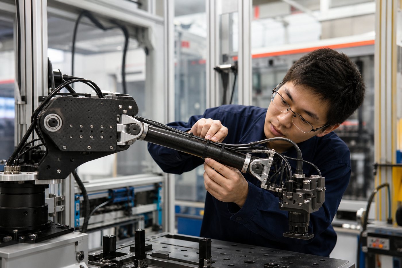
What Technical Support Does Not Replace
Technical support helps identify a practical material and manufacturing direction. It does not replace the application owner’s responsibility for final design authority, safety factors, regulatory approval and validation of the finished product.
No Universal Part Properties
Fiber datasheet values cannot be treated as guaranteed properties of every finished component.
Loads Must Be Defined
The customer should provide realistic loads, supports, duty cycles and failure consequences.
Critical Uses Need Validation
Safety-critical and regulated products may require qualified analysis, testing and certification.
Project-Specific Commitments
Tolerance, temperature, life and performance are confirmed only in the approved project scope.
Continue Your Carbon Fiber Engineering Review
Material Selection Guide
Compare fiber grades, weave, layup, resin, product form and process.
Frequently Asked Questions
Review common questions about materials, products, manufacturing and orders.
Custom Carbon Fiber Parts
Explore made-to-drawing components, machining, inserts and assemblies.
Manufacturing Capabilities
Review the product and processing capabilities available for OEM projects.
Common Questions Before a Technical Review
Send the drawing or CAD file, application, load directions, environment, quantity, tolerances, interfaces, surface requirements and validation needs. Identify assumptions that have not yet been confirmed.
Yes. The review can identify geometry, tooling, laminate, machining, assembly and inspection points that may affect feasibility or quotation. Drawing changes remain subject to customer approval.
Material direction can be reviewed from the loads, stiffness target, environment, geometry, process and budget. Final selection uses the exact available material and the agreed validation plan.
Prototype and low-volume projects can be evaluated. Tooling, setup and validation requirements depend on the geometry, manufacturing route and expected transition to production.
Yes. Provide insert geometry, material, loads, temperature, environment and assembly requirements. Bond area, preparation, isolation and inspection should be addressed together.
Tolerance depends on size, laminate, tooling, cure, machining datum, feature type and inspection method. Critical values must be reviewed on the drawing rather than assumed from a universal tolerance.
Not automatically. Analysis, testing, regulated approval and certification must be specifically defined and assigned. General manufacturing support should not be treated as final certification of the customer’s application.
Request Carbon Fiber Engineering Support
Send your drawing, CAD file, application, loads, environment, interfaces, quantity and critical requirements. Carbosources will review the material and manufacturing direction for quotation.