
The right manufacturing process depends on part geometry, load direction, laminate requirements and production quantity.
Carbosources reviews these factors together when planning custom carbon fiber tubes, sheets, profiles and machined components. Tooling, forming, curing, secondary machining and assembly must work together to produce a part that meets its drawing and acceptance requirements.
Explore the manufacturing routes below, then share your application and drawing for a project-specific review.
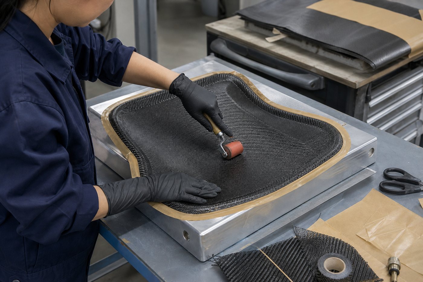
Geometry helps narrow the available carbon fiber manufacturing methods. Loads, interfaces and production requirements determine which route is appropriate.
| Part Form | Manufacturing Direction to Review | Important Inputs |
|---|---|---|
| Tubes | Roll wrapping, pultrusion or another suitable tube-forming route | Inside and outside dimensions, wall thickness, length, loads and end connections |
| Rods and Constant Profiles | Pultrusion where the cross-section and reinforcement requirements are suitable | Complete section drawing, length, fiber direction and connection details |
| Flat Components | Laminate preparation followed by CNC cutting and machining | Thickness, layup requirements, hole patterns, datums and edge condition |
| Molded Shapes | A suitable tooling, layup and molding approach | 3D geometry, release conditions, visible surfaces, interfaces and quantity |
A similar outside shape does not necessarily mean two parts should use the same construction. For example, tubes intended for axial loading, torsion or local clamping may require different reinforcement arrangements.
Each process offers a different combination of geometry, reinforcement control, tooling requirements and production considerations.
| Process | Typical Part Forms | Main Decisions |
|---|---|---|
| Roll Wrapping | Tubes and suitable mandrel-defined shapes | Ply orientation, mandrel geometry, wall construction and end interfaces |
| Pultrusion | Rods, tubes and constant-section profiles | Cross-section, reinforcement arrangement, tooling and cut length |
| Compression Molding | Suitable molded components | Material form, charge or layup arrangement, mold geometry and forming conditions |
| Prepreg Layup and Curing | Panels, shells and other suitable composite shapes | Ply sequence, tool surface, compaction and material-specific cure requirements |
| CNC Machining and Assembly | Finished plate parts, machined tubes and connected components | Datums, holes, slots, trimming, inserts and assembly alignment |
These routes are not all alternatives at the same stage. A molded part may still need CNC trimming and drilling, while a tube may require bonded fittings after manufacture. The final process plan should cover the complete component.
The carbon fiber roll wrapping process places reinforcement around a mandrel before compaction and curing. The mandrel helps establish the internal geometry, while the laminate and subsequent operations influence the wall and outside surface.
Roll wrapping can be considered for tubes requiring a defined laminate rather than a reinforcement arrangement chosen only for longitudinal loading. Fiber orientations are selected around the actual bending, torsional, transverse and connection requirements.
An outside diameter used for a sliding or clamped fit should be identified as a functional dimension. Likewise, a bonded internal fitting requires consideration of the tube’s inside geometry and available bond area.
The carbon fiber pultrusion process pulls continuous reinforcement through a forming and curing system to produce a continuous profile that is cut to length.
It is a manufacturing direction for suitable rods, tubes and profiles with a constant cross-section.
Pultruded construction often places substantial reinforcement along the profile’s length. Transverse, shear and connection requirements still need to be addressed through the selected reinforcement and component design.
A profile intended to carry axial loads should not automatically be treated as suitable for high local clamp pressure or a heavily loaded drilled joint.
Provide the full cross-section, including wall thicknesses, radii and internal features. State the cut length, quantity, load direction and any straightness or twist requirements that affect assembly.
Show holes, notches, slots and end connections on the drawing. These features may require secondary machining and can interrupt the reinforcement.
Carbon fiber compression molding uses a matched tooling arrangement and applied pressure to form suitable material into the required geometry. The material system determines the relevant processing and curing conditions.
The term covers different material forms. Continuous-fiber prepreg and chopped-fiber molding materials should not be treated as interchangeable constructions.
Material placement, fiber continuity, flow where applicable, thickness changes and mold geometry all affect the manufacturing approach.
For continuous reinforcement, ply placement and the ability to conform to the shape require attention. For a material that flows during molding, the flow pattern and resulting fiber distribution need separate consideration.
Include the 3D model, critical dimensions, visible surfaces, inserts, anticipated quantity and performance requirements. Identify areas where fiber continuity or a particular laminate is required.
Tooling cost and development work should be assessed alongside the intended production quantity. Suitability is confirmed for the specific part rather than assumed from its size or appearance.
Prepreg reinforcement contains a controlled resin system before it is laid into or onto a tool. The carbon fiber prepreg layup process involves preparing plies, positioning them in the required sequence, consolidating the layup and curing it under suitable conditions.
The surface fabric does not define the entire construction. Internal ply directions, material selection, thickness and local reinforcement must relate to the part’s loads and interfaces.
Curved parts also require attention to ply drape, internal radii and areas where material may bridge or wrinkle.
Oven and autoclave curing are processing options, not universal quality rankings. Autoclaves can apply additional external pressure; out-of-autoclave processing requires materials and procedures suited to that route.
Storage, handling, compaction and cure requirements should follow the selected material system and approved manufacturing plan. A cure schedule from one resin system should not be assumed suitable for another.
For a custom component, provide the geometry, laminate requirements, surface expectations and operating environment so a suitable layup and curing route can be reviewed.
Carbon fiber fabrication processes often continue after the laminate or profile has been formed.
Secondary operations can establish the final outline, hole pattern, slots, pockets, trimmed edges and interfaces needed for installation.
A correct outer shape does not guarantee that the part will assemble correctly. Identify the reference faces and hole locations that control fit.
Distinguish critical features from general contours so machining and inspection can focus on the dimensions that matter.
Carbon fiber trimming and drilling interrupt reinforcement. Hole position, edge distance, workholding and machining condition should therefore be considered with the laminate.
Threaded or removable connections may require separate fittings, bonded inserts or other drawing-defined interfaces. The connection method should be selected around load transfer and service requirements.
The following examples illustrate how manufacturing stages can connect. They are planning examples, not fixed production recipes.
| Example Component | Illustrative Manufacturing Route |
|---|---|
| Carbon Fiber Mounting Plate | Laminate preparation → CNC cutting and drilling → Edge finishing → Inspection |
| Tube with End Fittings | Tube manufacture → Cut-to-length and end machining → Fitting assembly → Dimensional and alignment checks |
| Curved Cover | Tool preparation → Layup and forming → Trimming and drilling → Surface finishing and inspection |
Planning the complete route helps identify requirements that might otherwise be missed between operations. A hole pattern may need a machining datum, while an end fitting may determine the tube’s internal fit and finished assembly length.
Axial, bending, torsional and local connection loads influence the required reinforcement. A manufacturing route must support the intended laminate and load path.
Constant sections, curved surfaces, enclosed features and release conditions affect tooling and process feasibility.
Fiber orientation, material form, thickness and resin requirements can narrow the available manufacturing options.
Some dimensions are controlled primarily during forming. Others may require secondary machining. Identify the features that locate, clamp, slide or bond to another component.
Prototype quantities and repeat production may justify different tooling approaches. The development plan should identify any changes between the sample route and intended production route.
Visible faces, bonding surfaces, temperature, moisture and other exposure requirements should be included in the initial review.
Start with the part geometry, loads, material requirements, interfaces and quantity. A drawing and application description allow these factors to be reviewed together. A photograph alone usually leaves important construction and acceptance requirements undefined.
Sometimes, but similar dimensions do not establish equivalent laminate behavior. Compare the reinforcement, resin, dimensional requirements and connection details rather than selecting solely by appearance.
No. Some parts can be machined from suitable sheet or profile material. Other projects may use compatible existing tooling. New geometry or construction requirements may need dedicated forming tools or secondary fixtures.
Drawing-defined outlines, holes, slots, pockets and precise interfaces may require machining after forming. The appropriate sequence depends on tool access, laminate construction and how the part will be located and inspected.
They can, but the differences must be understood. A sample made by another route may help evaluate shape or fit without establishing production performance. Material, tooling or process changes may require additional validation.
Send your drawing or CAD model together with:
Carbosources can review these inputs to propose a manufacturing direction and identify the tooling, sample work and secondary operations that need to be included in the project scope.
Related Capabilities: Technical Support · Quality Control & Inspection