
Home › Frequently Asked Questions
Carbon Fiber Manufacturing Frequently Asked Questions
Find practical answers about custom carbon fiber materials, tubes, rods, sheets, drawings, prototypes, tooling, CNC machining, bonded inserts, tolerances, quality control, OEM production and quotations.
Every project is different. Use these answers to prepare your requirements, then send the drawing and application details for a project-specific manufacturing review.
Drawings & CAD · Materials · Prototypes · CNC & Bonding · Inspection · OEM Supply
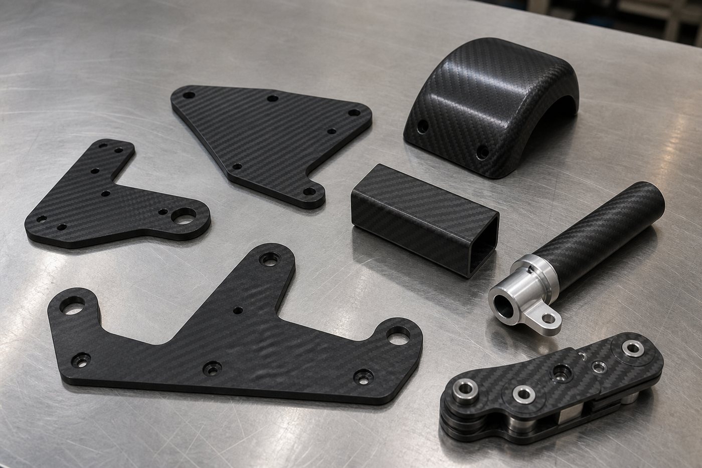
Find Answers for Your Carbon Fiber Project
Custom Projects
Drawings, CAD files, samples and engineering review
Materials
Fiber grade, weave, layup, resin and finish
Products
Tubes, rods, sheets and custom components
Manufacturing
Tooling, pultrusion, roll wrapping and molding
Machining & Assembly
CNC, holes, inserts, bonding and hardware
Quality
Tolerance, inspection, testing and approval
Orders & Shipping
MOQ, lead time, repeat supply and packaging
Request a Quote
Information needed for a useful quotation
Custom Projects · Materials · Products · Manufacturing · Machining · Quality · Orders
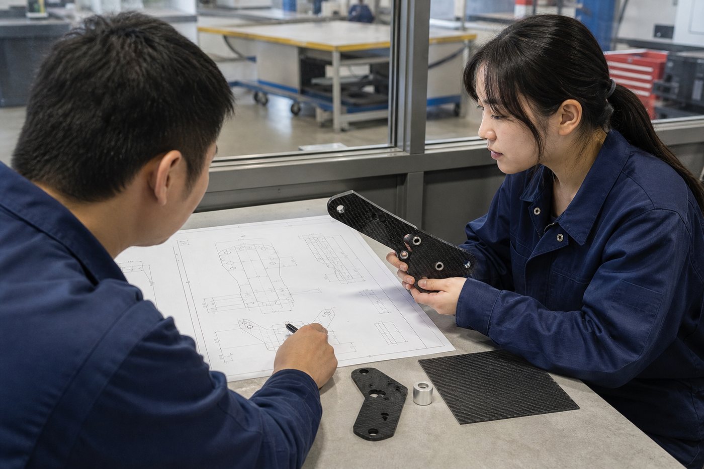
Custom Carbon Fiber Project FAQ
Start here if you have a drawing, CAD model, sample part or application requirement.
Yes. Send a dimensioned drawing together with the application, quantity, material assumptions, critical tolerances and inspection requirements. Carbosources reviews the geometry, manufacturing route, laminate direction, interfaces and commercial scope before quotation.
A 3D CAD file helps communicate geometry, but it may not define tolerances, datums, surface class, loads or acceptance criteria. A 2D drawing or written specification should accompany the model when those details are important.
A sample can support geometry and finish review, but it does not reveal every material, hidden interface or structural requirement. Reverse-engineering feasibility depends on access, measurement, tooling, intellectual-property rights and the required level of replication.
Carbosources can review the application, geometry, loads, environment, target quantity and assembly interfaces to propose a practical product form and manufacturing direction. Final engineering responsibility and validation scope should be agreed for the specific project.
Common neutral 3D formats and dimensioned PDF drawings can normally be reviewed. Confirm the available file format before sending proprietary data so the engineering team can avoid translation or revision-control problems.
Provide the application, load directions, stiffness or weight target, operating environment, quantity, critical dimensions, surface requirements, joining method, inspection needs and delivery destination. Mark any dimensions that directly control fit or function.
Confidentiality requirements can be discussed before detailed drawings are exchanged. Identify the parties, project scope and information to be protected so the appropriate commercial process can be followed.
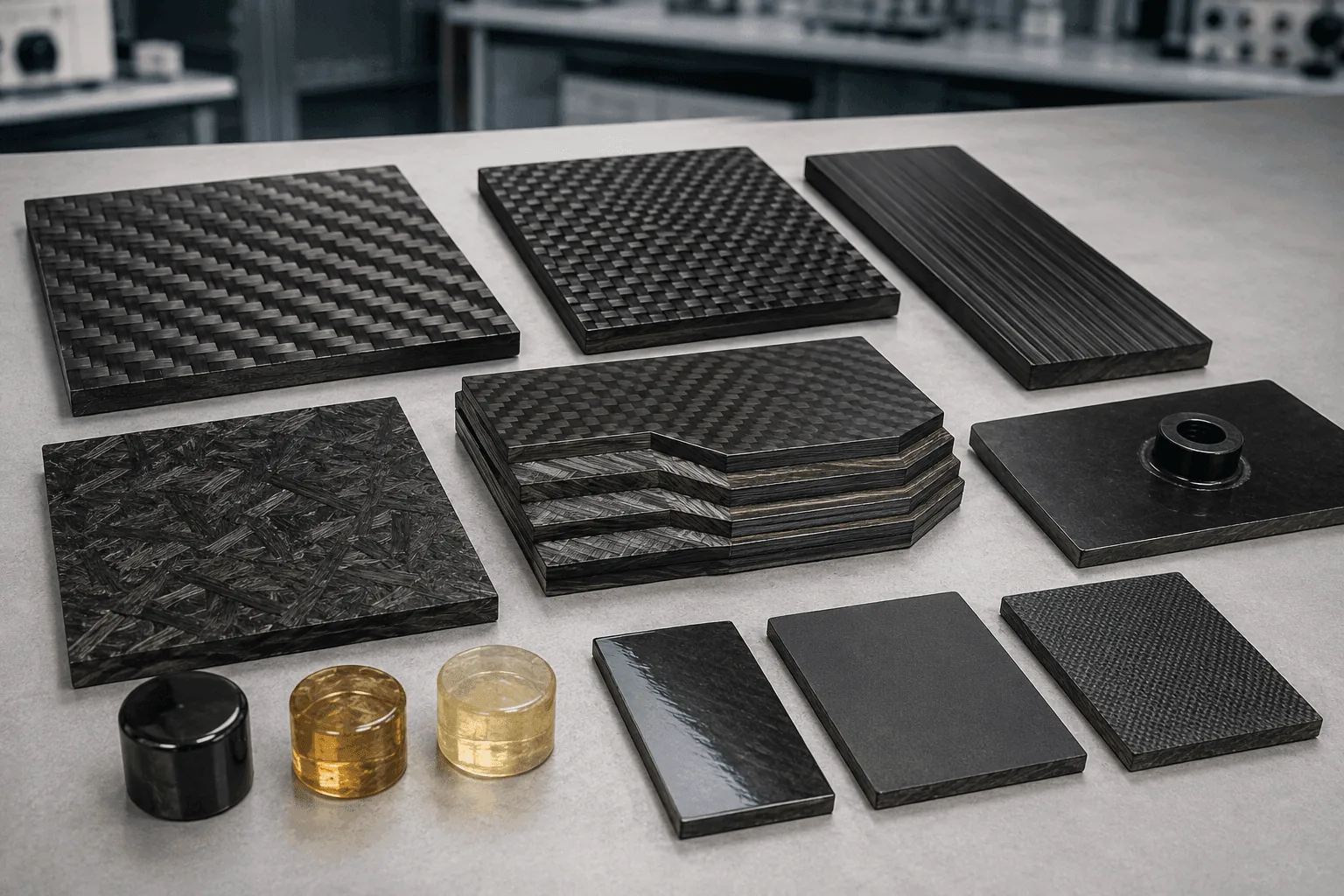
Carbon Fiber Material FAQ
Material grade, reinforcement format, layup and resin must be selected as one system around the application.
Begin with loads, stiffness, geometry, environment, interfaces, quantity and manufacturing process. Then select the fiber grade, UD or woven reinforcement, ply directions and resin system. The most expensive fiber is not automatically the best choice.
T700S has higher typical tensile strength than T300 while both are commonly classified as standard-modulus fibers. The better choice depends on the complete laminate, strain requirements, cost, availability, process and validation plan.
Strength relates to the stress at failure under a defined test. Modulus describes elastic stiffness. A material can be stronger without being proportionally stiffer, so the selection should match whether failure load or deflection controls the design.
K-count describes the approximate number of filaments in a tow, not a complete quality or strength grade. Compare the actual fiber, fabric construction, areal weight, resin, fiber volume and finished laminate rather than the K-count alone.
UD reinforcement is efficient when the main load direction is known. Woven fabric places fibers in multiple directions and may improve handling or appearance. Many engineered laminates combine a woven face with internal UD or multi-angle plies.
Plain weave has frequent interlacing and good fabric stability. Twill has a diagonal pattern and often drapes more easily over selected contours. Appearance, handling and laminate design should be considered separately from the underlying fiber grade.
The resin transfers load between fibers, protects the reinforcement and influences cure, temperature, moisture, chemicals, toughness, finish and bonding. Critical environments require review of the exact resin-system data and manufacturing process.
Carbon Fiber Tubes, Rods, Sheets and Custom Parts FAQ
Use these answers to identify the right product family before requesting a custom specification.
Round, square, rectangular, hexagonal and selected project-specific profiles can be reviewed. Feasibility depends on dimensions, wall thickness, laminate, length, process, tooling and order quantity.
Custom OD, ID, profile, wall and length can be evaluated from a drawing. Load direction, stiffness, buckling, joining and manufacturing constraints should be reviewed before fixing the dimensions.
Pultrusion suits continuous profiles with reinforcement concentrated along the production direction. Roll wrapping allows a tailored ply schedule around a mandrel. The appropriate route depends on geometry, loads, finish, tolerance and quantity.
Solid round rods, square rods, pultruded profiles and rods with bonded metal interfaces can be reviewed. Specify diameter or profile, length, straightness, loads, end features and expected quantity.
Options may include woven laminates, unidirectional sheets, flexible veneers, colored surfaces and CNC-machined sheet parts. Thickness, layup, finish, flatness, machining and application determine the right format.
Yes. Profiles, holes, slots and selected countersinks can be machined from a suitable laminate. Edge distance, tool access, dust control, workholding and the relation between fiber direction and geometry must be considered.
Custom flat, tubular, constant-section and molded components can be evaluated from drawings or samples. Geometry, tooling, fiber continuity, trim, interfaces, finish and production quantity determine the practical route.
Carbon Fiber Tubes
Round, square, hexagonal and custom lightweight profiles
Carbon Fiber Rods
Pultruded, square and threaded-interface solutions
Carbon Fiber Sheets
Woven, UD, flexible, colored and CNC-cut formats
Custom Carbon Fiber Parts
Made-to-drawing components and assemblies
Carbon Fiber Manufacturing Process FAQ
The process must match part geometry, fiber architecture, tooling, surface class and planned production quantity.
Depending on the product, Carbosources can review pultrusion, tube-forming routes, prepreg or molded processing, vacuum-assisted methods, sheet machining and secondary assembly. Availability is confirmed for the actual drawing and scope.
Pultrusion is useful for continuous rods and profiles with a constant cross section, especially when axial reinforcement and repeat production are important. Transverse, torsional and connection requirements still need separate review.
Roll wrapping is commonly considered for tubes that need a controlled wall and multiple ply directions around a mandrel. Diameter, taper, length, finish, extraction and order volume affect feasibility.
No. Flat components can be machined from sheet and constant profiles may use pultrusion or tube processes. Complex three-dimensional surfaces generally need dedicated tooling or a suitable existing mold.
Prepreg contains reinforcement pre-impregnated with a controlled resin system. Storage, handling, layup, compaction and cure conditions must match the material. The term “prepreg” alone does not define the finished laminate performance.
The team reviews geometry, load path, fiber direction, finish, tolerance, tooling, production quantity, inspection and budget. Selecting a process before these inputs are known can create unnecessary cost or design limitations.
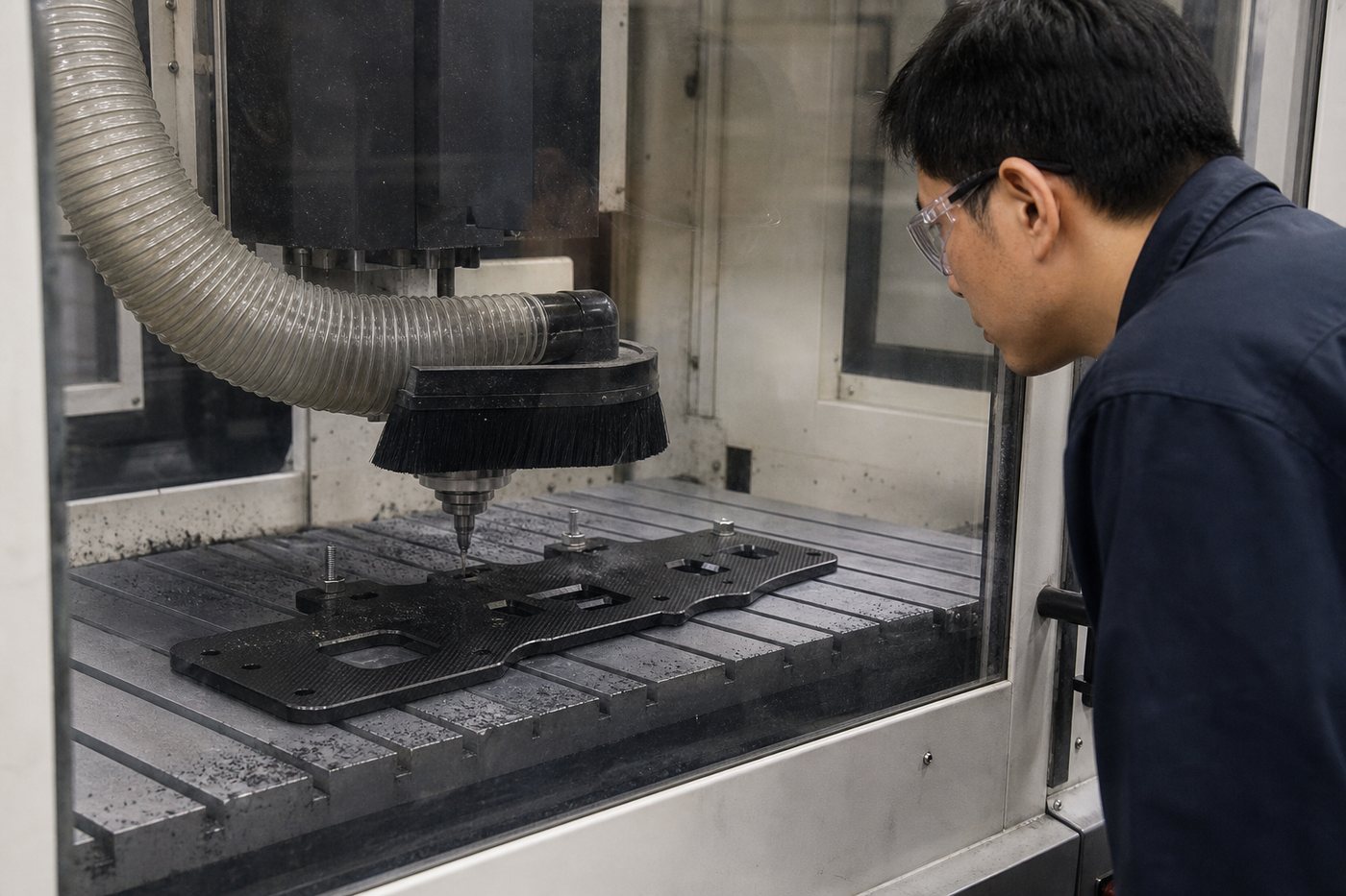
Carbon Fiber CNC Machining, Bonding and Insert FAQ
Secondary processing should be planned with the laminate and joint design, not added as an afterthought.
Yes. Carbon fiber laminates can be routed, drilled and trimmed with suitable tooling, workholding and dust extraction. The laminate, thickness, edge distance, tolerance and surface requirements affect the machining plan.
These features can be reviewed from the drawing. Hole size, edge distance, laminate direction, fastener load and backing support matter because local damage or delamination can control the joint.
Tool geometry, sharpness, support, feed, entry and exit conditions, workholding and laminate quality all influence the edge. Critical features should be inspected against agreed acceptance criteria.
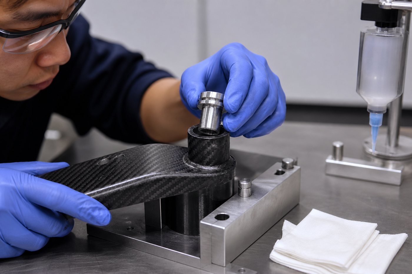
Yes, when insert geometry, bond area, adhesive, surface preparation, load transfer, temperature and corrosion environment are reviewed. Pull-out or torque validation can be included when required by the project.
It can, but the joint must address adhesive compatibility, surface preparation, differential movement, moisture and galvanic interaction. Isolation and sealing may be required depending on the environment.
Selected parts can be supplied with approved inserts, fittings, hardware or bonded subcomponents. Assembly scope, customer-supplied hardware, torque, inspection and packaging should be defined on the drawing or purchase specification.
Carbon Fiber Parts with Metal Inserts
Threaded inserts, bushings and bonded fittings can simplify final assembly when the joint is designed around load transfer, bond geometry and the operating environment.
Carbon Fiber Tolerance and Quality FAQ
Acceptance criteria should be defined from the drawing, process and functional risk of the component.
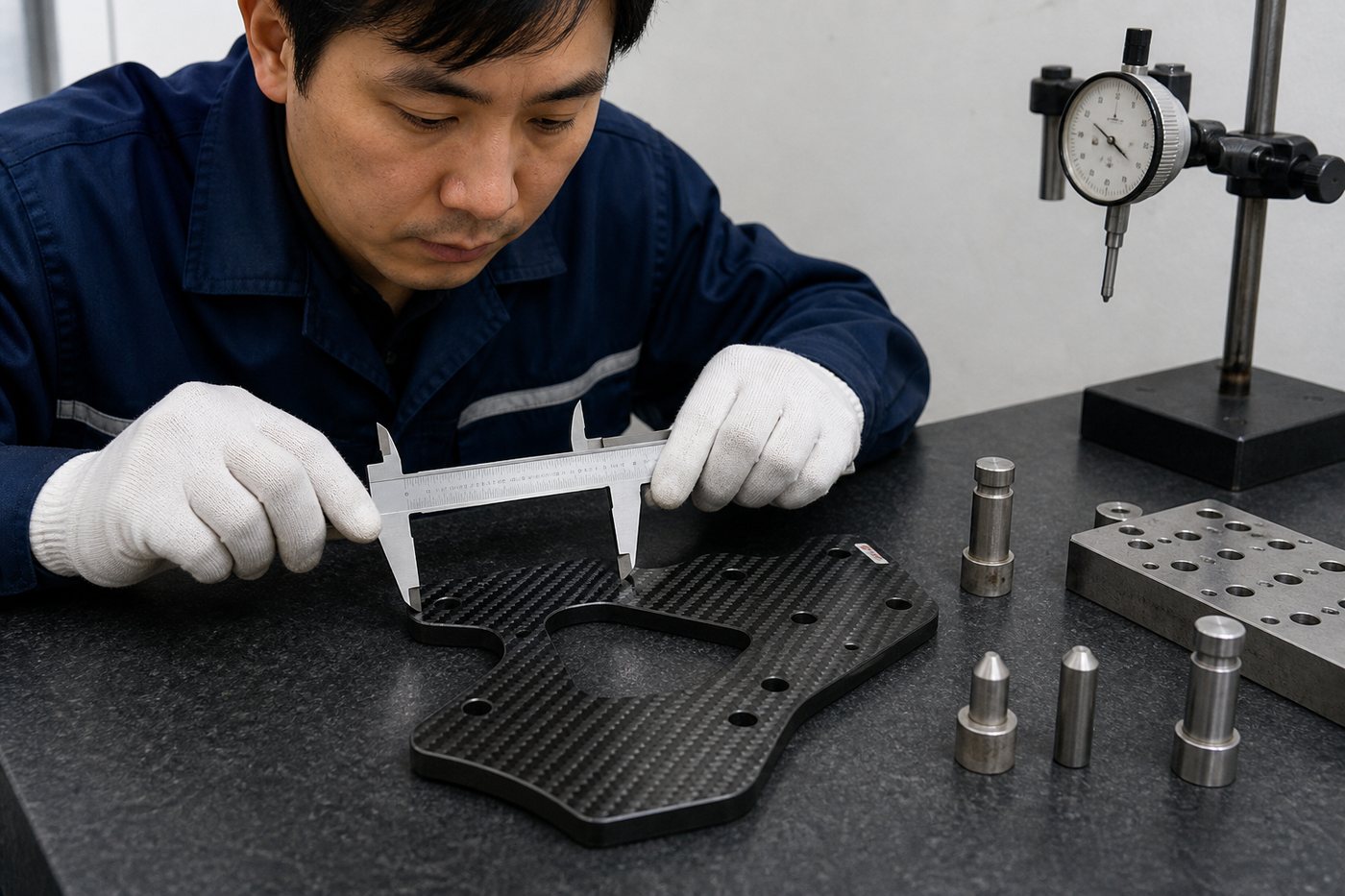
Tolerance depends on part size, laminate, tooling, cure, machining datum, feature type and inspection method. Critical values must be reviewed on the drawing; one universal tolerance should not be applied to every CFRP product.
Inspection may use suitable dimensional tools, fixtures or coordinate-based methods according to the feature and agreed scope. Datums, sampling and acceptance limits should be defined before production.
Cosmetic criteria can cover weave alignment, resin-rich areas, marks, gloss, coating and permitted visual variation. Reference samples or written acceptance criteria help avoid subjective decisions.
Documentation can be discussed during quotation. Identify the required dimensions, sampling plan, report format, material documents and any customer-specific forms before the order is accepted.
Position, bond-line condition and visible workmanship can be inspected. Functional pull, torque or proof testing is provided only when the method, load, sampling and acceptance criteria are included in the project scope.
Yes. A prototype or first-article stage can be used to confirm dimensions, fit, surface, interfaces and process assumptions before repeat production. Approval criteria and revision status should be recorded.
Quotation, MOQ, Lead Time and Shipping FAQ
Commercial details depend on geometry, process, tooling, quantity, inspection and delivery requirements.
Send the drawing or CAD file, application, dimensions, quantity, loads, environment, tolerance, finish, interfaces, inspection requirements and delivery destination. State whether the request is for a prototype, annual demand or repeat order.
Important cost drivers include material, laminate complexity, tooling, cure or process time, machining, inserts, finish, inspection, quantity, packaging and documentation. A clear specification produces a more meaningful quotation.
Prototype and small-batch projects can be reviewed, although tooling and setup may still be required. The most practical route depends on geometry, validation needs and the expected path to production.
MOQ is project-specific. Standard products, custom profiles, machined sheet parts and molded components have different material, tooling and setup constraints. Send the target prototype and annual quantities for review.
Lead time depends on material availability, drawing approval, tooling, prototype validation, process capacity, machining, inspection and shipping. A confirmed schedule should be based on the approved technical and commercial scope.
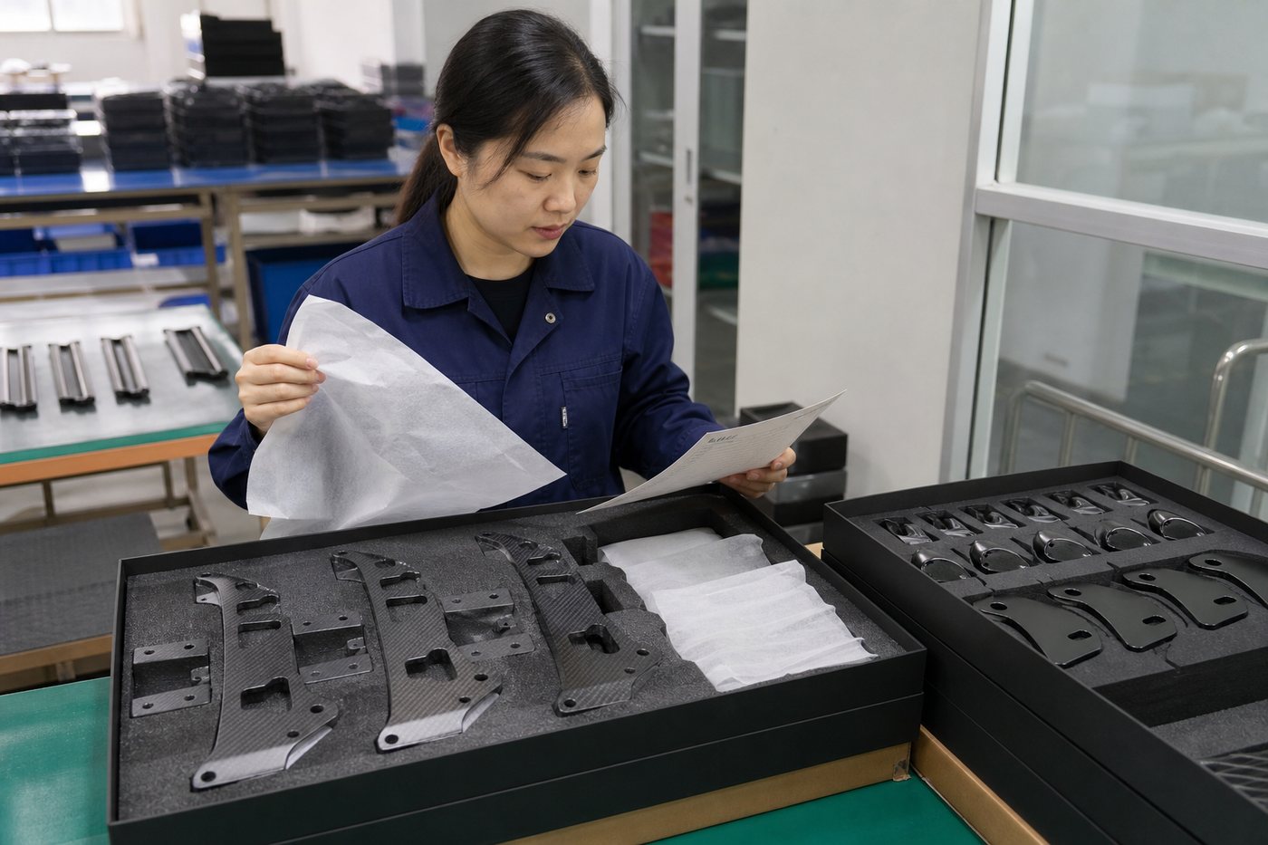
Packaging is selected around part shape, surface, length, quantity and transport risk. Protective separation, rigid support, identification and export packaging can be discussed for the order and delivery destination.
Yes. After prototype approval, the drawing, process, tooling, inspection and packaging requirements can be frozen for repeat supply. Revision control is important whenever geometry or acceptance criteria change.
Need More Help Choosing Carbon Fiber?
Compare fiber grades, modulus, weave, tow size, layup direction, resin systems, product forms and manufacturing processes in the complete selection guide.
Ask Carbosources About Your Carbon Fiber Project
Send your drawing, dimensions, application, loads, environment, quantity and target schedule. We will review the material, manufacturing process and quotation requirements for your project.