
Home / CNC Machined Parts / Carbon Fiber Angle Brackets
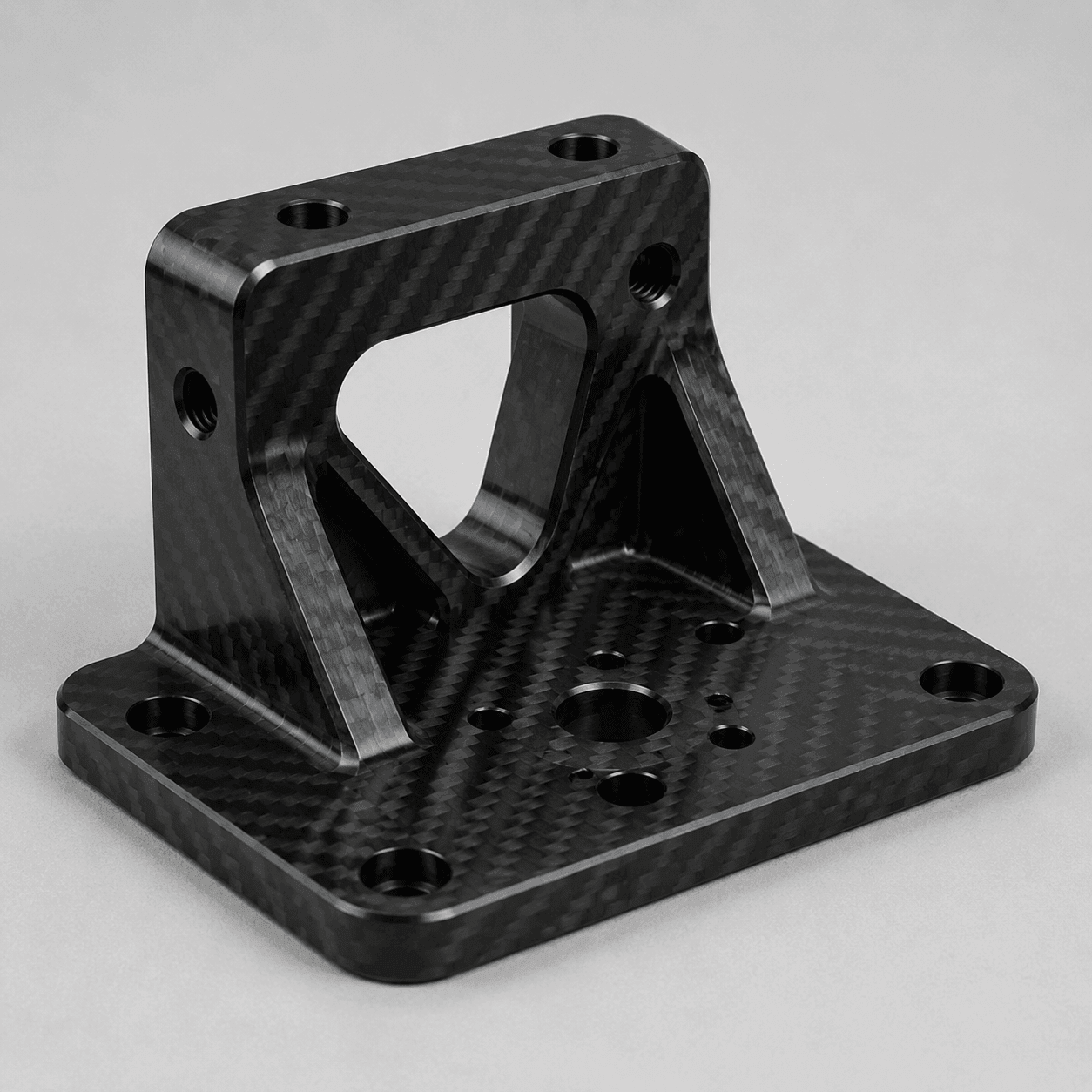
Illustrative bracket geometry. Final construction follows the agreed drawing.
CUSTOM CARBON FIBER COMPONENTS
Custom carbon fiber angle brackets for mounting interfaces and lightweight assemblies. Define the leg dimensions, laminate requirements and mounting features for a drawing-based quotation.
| Product | Custom angle / L bracket |
|---|---|
| Geometry | Leg lengths, width and inside radius |
| Machining | Mounting holes, slots and profiles |
| Specification | Confirmed against your drawing |
Send your drawing, quantity and loading requirements.
Define the mating faces, installation envelope and required angle.
Specify fiber directions and loading needs alongside thickness.
Coordinate hole patterns, slots and fastener access.
Include loads, environment and inspection requirements.
CUSTOM SPECIFICATIONS
| Parameter | Include in your drawing |
|---|---|
| Overall geometry | Both leg lengths, bracket width and included angle |
| Laminate | Thickness and required ply schedule / material |
| Inside corner | Radius and clearance to the mating component |
| Mounting features | Hole diameter, position, slots and fastener type |
| Assembly fit | Datums, mating faces and critical tolerances |
| Service conditions | Load direction, offset, temperature and moisture |
| Order scope | Prototype / production quantity and required date |
Attach a 2D drawing and, where available, a 3D model. Mark critical dimensions and show the assembly interface.
Dimensions, tolerances, finish, minimum quantity and lead time are confirmed after review.
LAMINATE & CONSTRUCTION
The laminate schedule matters as much as the outside dimensions. A 0°/90° arrangement places reinforcement along two principal directions; adding +45° and −45° plies changes the response to off-axis loading. DragonPlate distinguishes its 0°/90° angle stock from balanced, symmetrical quasi-isotropic angle laminates for this reason.
For your carbon fiber L bracket, identify the main load direction and whether the assembly also experiences twisting or changing loads. Include a required ply schedule if your design already defines one. Surface weave appearance alone is not a complete laminate specification, and a quasi-isotropic in-plane arrangement does not make the through-thickness properties identical to the in-plane properties.
A formed angle requires reinforcement to follow the internal corner. Very tight radii make this harder to manufacture; the radius therefore belongs on the drawing alongside thickness and leg length. Treat the curved region as part of the laminate design, rather than simply copying the sharp inside corner of a machined metal bracket.
Also distinguish a molded angle from an assembly of separate components. These routes create different joints and load paths. A cured thermoset carbon fiber plate should not be assumed to bend into an L shape by reheating. CNC machining can finish an angle’s holes and outline, but does not itself establish the corner construction.
CNC MACHINING
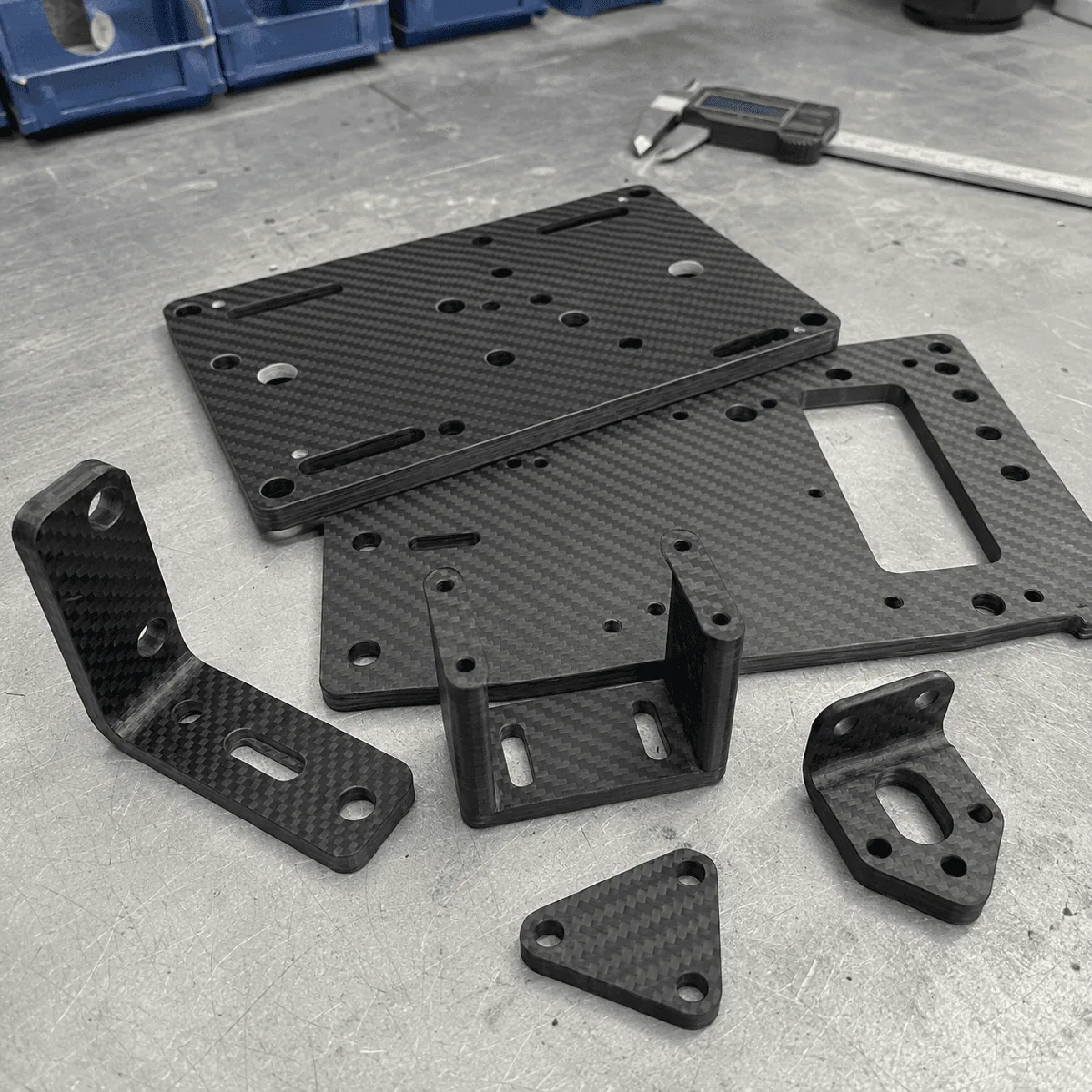
Related plate and bracket geometries from the media library.
Adding a mounting hole changes the load path through the laminate. In a bolted connection, the material can crush locally against the bolt (bearing), fail across the remaining width beside the hole (net-section tension), or tear toward a nearby free edge (shear-out).
Use clear drawing definitions: D is hole diameter, e is the hole-center distance to the loaded end, and w is the local part width. Research on carbon/epoxy joints shows that e/D and w/D affect joint behavior. A universal minimum edge distance cannot be selected from the term “carbon fiber” alone; laminate and loading details matter.
For slots or lightening cutouts, show the remaining material between the opening, mounting holes and outer edge. Increasing hole diameter to accommodate a larger bolt also removes material, so it is not automatically a stronger solution.
A hole can meet its diameter requirement and still have damaged laminate around the entry or exit. As a drill breaks through, the remaining plies have less support and can separate under drilling thrust. Supporting the exit face with a suitable backing plate and controlling feed near breakthrough are established approaches to reducing exit delamination.
Composite machining also requires suitable cutting tools. Rock West describes carbide drills and carbide or diamond tooling for relevant composite operations. Tool selection and cutting conditions should match the actual laminate; a single spindle-speed recommendation is not a substitute for process qualification.
On the drawing, identify hole size and position separately from acceptable edge damage. Ask for both hole faces to be checked for breakout, lifted plies and fiber pull-out. Agree how damage will be assessed where a joint is structurally critical.
FASTENING & ENVIRONMENT
Do not treat a carbon laminate like a metal block when specifying a tapped hole. Easy Composites recommends bonded threaded inserts instead of directly tapping composite laminate. Bonded fasteners can spread load over a larger footprint and, in suitable arrangements, avoid cutting through reinforcement.
Specify whether your assembly uses through-bolts and nuts, bonded studs or threaded inserts. Include access for the nut or installation tool and the required insert arrangement. These are connection options for review, not interchangeable drop-in details.
Clamping also matters: composite through-thickness behavior differs from its in-plane response. Excessive preload can damage the laminate locally. Select the bearing footprint and tightening procedure for the actual joint rather than copying a torque from an all-metal assembly.
Carbon fiber can form a galvanic couple with certain metals when there is electrical contact and an electrolyte such as moisture. Review exposed metal-to-carbon interfaces, including fasteners. An insulating glass-fiber layer or an appropriate coating may be part of the interface design; protection needs to cover the actual contact path.
Temperature and moisture can also change laminate properties and joint preload. Include the service environment in the RFQ, particularly for outdoor equipment or assemblies near heat sources. A room-temperature material value does not by itself establish suitability across the operating range.
LOAD CASE EXAMPLE
ILLUSTRATIVE CALCULATION
At a 100 mm offset, the same 20 N force produces 2 N·m.
Double the perpendicular offset → double the moment.
Applied moment only; not a bracket load rating.
Illustrative calculation, not a Carbosources load rating. Suppose a transverse force of 20 N acts 50 mm from a mounting reference. The moment about that reference is M = F × L = 20 × 0.05 = 1 N·m. Moving the same force to 100 mm doubles the moment to 2 N·m.
This explains why “supports 20 N” is incomplete information for an angle bracket. The force position matters. Send the load direction and offset, mounting points and permitted movement with the drawing. This simple calculation identifies an applied moment only; it does not establish bracket strength, bolt loads, fatigue life or a safety factor.
DRAWING & INSPECTION
Specify the acceptance requirements for your assembly. The following are review points, not a statement of a standard Carbosources inspection package.
Leg dimensions, included angle, radius and mating-face requirements.
Datums, center distances, diameter and slot dimensions.
Entry / exit damage, lifted plies, breakout and fiber pull-out.
Fasteners, contact footprint and any agreed functional validation.
FAQ
Yes. Include hole sizes, positions, slot dimensions and critical tolerances in your drawing. Feasibility and machining access will be reviewed before quotation.
An L bracket generally has two mounting faces at 90 degrees. Angle bracket is a broader term; confirm the included angle and corner geometry in the drawing.
This page presents a custom quotation offering. Price, quantity requirements and lead time depend on the approved design, material and manufacturing route.
No. An image does not establish load capacity. Provide the loads, mounting conditions and acceptance requirements so the design and any required validation can be discussed.
Mark the two mating faces, the internal radius, hole datums, loaded end distance and any clearance envelopes. State the laminate requirement separately from cosmetic finish. Include the fastener arrangement and the dimensions that determine assembly fit, then specify inspection requirements for those features.
FURTHER INFORMATION
The engineering explanations draw on the following sources. Their product specifications are not Carbosources specifications.
DragonPlate — Carbon Fiber Angle · Composites Knowledge Network — Shape Development · Rock West Composites — Cutting Carbon Fiber · Study on Bearing Strength and Failure Modes of Single Bolted Joint Carbon/Epoxy Composite Materials · Research on exit backing and drilling delamination · Easy Composites — Bonding Fasteners · Composites Knowledge Network — Environmental Effects and Galvanic Corrosion
REQUEST A QUOTE
Send the drawing, required quantity, mounting arrangement and service conditions. We will review the request before confirming feasibility, price and lead time.