
Home › Carbon Fiber Rods › Carbon Fiber Strips
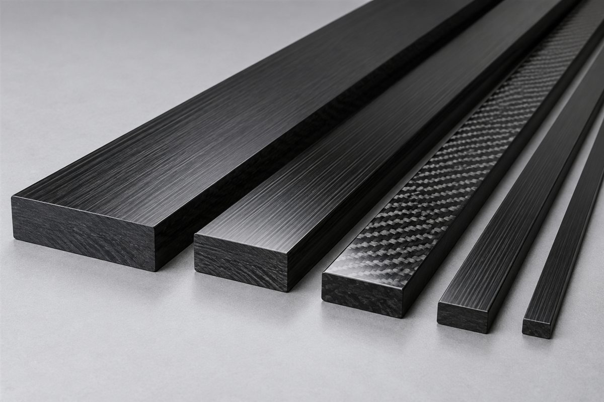

SOLID RECTANGULAR CFRP PROFILES SPECIFIED FOR THE LOAD PATH
Custom Carbon Fiber Strips and Flat Bars
Carbosources develops custom carbon fiber strips and solid carbon fiber flat bars for OEM structures that need low mass, longitudinal stiffness and a drawing-controlled rectangular section. Projects can begin with an economical pultruded profile or with strips cut from a laminated sheet when holes, transverse loads or a multidirectional layup change the requirement.
A useful request defines more than width and thickness. Send the support span, load direction, installed orientation, connection method, finished length, machining features, quantity and environment. These inputs allow the strip construction, section, edge condition and inspection plan to be reviewed together before quotation.
| Design input | What the RFQ or drawing should define |
|---|---|
| Section | Finished width, thickness, length, corner or edge condition and the dimensions that control the fit |
| Construction | Pultruded UD profile, laminate-cut strip or a required fiber-orientation concept |
| Load case | Tension, compression, flatwise or edgewise bending, torsion, side load, impact and duty cycle |
| Installation | Which face is supported, unsupported span, clamping method, adhesive joint or fastener geometry |
| Machining | Cut length, holes, slots, chamfers, radii and datum-controlled feature positions |
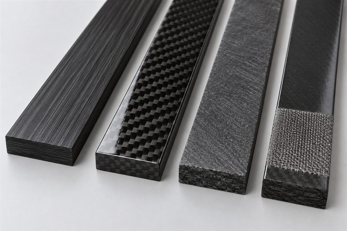
| Surface | Natural pultruded, matte, cosmetic woven, abraded or bonding-prepared zones |
| Environment | Operating temperature, moisture, chemicals, outdoor exposure and electrical contact |
| Acceptance | Width, thickness, length, straightness, flatness, edge appearance and requested tests |
Separate functional requirements from preferences. A woven surface may be wanted for appearance, but it does not define the internal reinforcement. Likewise, a thick strip is not automatically stiff enough unless the bending direction, span and support conditions are known. Carbosources reviews feasible constructions and tolerances against the drawing rather than assigning one universal rating to all carbon fiber reinforcement strips.
Choose Pultruded or Laminate-Cut Construction
Pultruded carbon fiber strips normally use continuous fibers running mainly along the length. This construction is efficient when axial stiffness, tensile load or bending along a consistent span controls the design. A constant section also suits repeat production and cut-to-length supply. Existing tooling is usually the practical starting point for prototypes and regular orders; a new width or thickness may require dedicated tooling and an appropriate production quantity.
A laminate-cut strip is machined from carbon fiber sheet. Its layup can include 0°, 90° and ±45° reinforcement where transverse load, torsion, holes or local fasteners make a predominantly longitudinal profile less suitable. It can also be practical for low-volume, unusual-width parts. Cutting a strip from sheet does not make it interchangeable with a pultruded profile: fiber architecture, edge condition, length availability and cost structure differ.
| Option | Useful when | Points to review |
|---|---|---|
| Pultruded UD strip | The primary load and stiffness direction runs along the part | Available tooling, transverse loading, end splitting and hole locations |
| Laminate-cut strip | The part needs multidirectional reinforcement, unusual width or prototype quantities | Layup, sheet size, cut-edge finish and machining allowance |
| Machined flat bar | The customer needs installation-ready holes, slots, chamfers or profiles | Datums, edge distance, fiber interruption and inspection method |
| Bonding-ready strip | The strip will be adhesively joined as a stiffener or reinforcement | Bonding zone, surface preparation, adhesive system and fixture plan |
Use Section Orientation to Control Bending
A rectangular section behaves differently depending on how it is oriented. When a strip bends across its thin dimension, it is in flatwise bending. Turning the same strip so its larger dimension acts as the section depth produces edgewise bending and can increase geometric bending stiffness substantially. The support envelope, attachment and stability still need to allow that orientation.
Thickness has a strong influence on the second moment of area in the bending direction, but section geometry alone is not a load rating. Material modulus, fiber direction, unsupported span, boundary conditions and local joints all contribute to deflection. For an early comparison, state the maximum allowable deflection and provide the real span and load position rather than selecting a strip only from a catalog width.
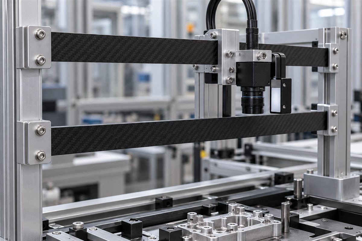
Consider a hypothetical inspection frame with an 800 mm unsupported span and a camera load near the center. If the flat bar can be mounted on edge, changing section depth can improve bending stiffness without simply making the entire profile wider. If the same part must fit flat under a cover, additional thickness, a different laminate or a second stiffener may be required. This example is a selection method, not a verified rating for a Carbosources product.
Compression members also need a stability review. A long narrow strip can buckle laterally before reaching the material compressive strength. Show the unsupported length, end restraint and expected side load so that section orientation and bracing can be considered.
Design Holes, Slots and Bonded Joints
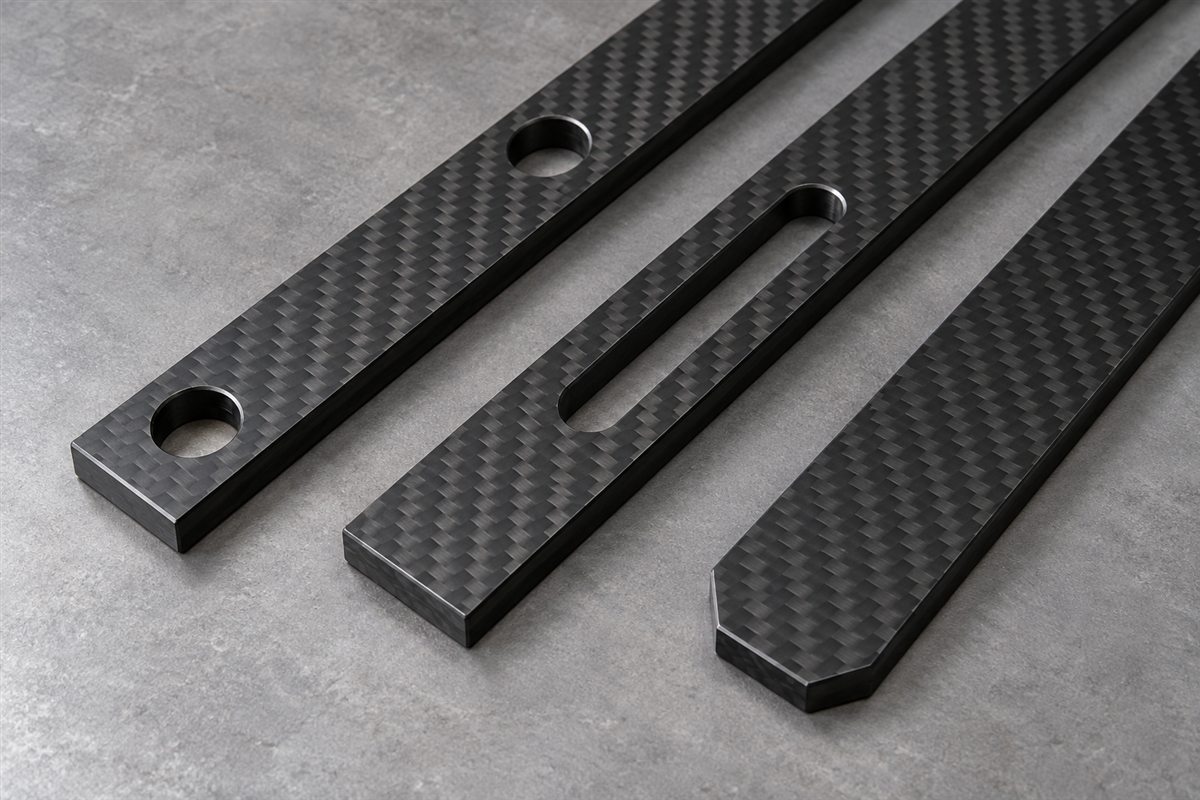
Drilling and slotting interrupt fibers and concentrate stress at the feature edge. For a predominantly unidirectional strip, holes close to an end or side edge can promote splitting. The drawing should identify hole diameter, edge distance, load direction, bearing surface and fastener clamp-up. When a fastened joint dominates the part, a multidirectional laminate or a locally redesigned interface may be more suitable than a narrow UD profile.
Carbosources can review cut-to-length supply, drilled holes, elongated slots, chamfered ends and drawing-based CNC machining. Machined edges should have a defined visual and dimensional acceptance condition. Avoid assigning a decorative edge radius where a mating block, washer or bond line needs a controlled flat surface. Related secondary processing is described on the carbon fiber CNC machining page.
Adhesive bonding distributes load differently from a bolt. Mark the complete bonding zone, overlap length and peel direction on the assembly drawing. A matte or lightly abraded appearance alone does not prove that a surface is ready for a particular adhesive. Surface preparation, cleaning, storage, adhesive choice, bond-line thickness, fixture pressure and cure conditions must form one controlled process.
Where a peel-ply-textured or factory-prepared area is requested, separate it from cosmetic zones and dimensions used for sliding or clamping. Carbon fiber is electrically conductive, so direct contact with dissimilar metals may also require environmental and galvanic-corrosion review. The joint design should include suitable isolation, coating or material selection when service conditions demand it.
What to Put on the Strip Drawing
- Geometry: finished width, thickness, length, corner condition and allowable mass.
- Orientation: which face is mounted, the bending direction and the required fiber direction.
- Loads: tension, compression, flatwise or edgewise bending, torsion, impact and duty cycle.
- Supports: unsupported span, contact length, clamps, fasteners, adhesive overlap and mating materials.
- Machining: hole and slot size, position, edge distance, chamfers, radii and datum scheme.
- Surface: natural, matte, cosmetic or bonding-prepared areas identified by zone.
- Environment: temperature, moisture, chemicals, UV exposure and metal contact.
- Acceptance: dimensional tolerances, straightness, flatness, appearance, sampling and requested tests.
Provide a dimensioned PDF with the drawing revision. DXF is useful for two-dimensional profiles, holes and slots; STEP or IGES helps show mating blocks and the installed assembly. Identify critical datums and functional tolerances rather than applying one tight tolerance to every dimension. State whether the supplied item is a straight cut strip, a machined component or a labelled kit of multiple lengths.
If the project starts from a standard section, provide the acceptable width and thickness range so existing tooling can be reviewed. For a new section, include prototype demand and forecast production quantity. If the required part is a wider plate rather than a narrow solid profile, compare the available carbon fiber sheets before selecting the manufacturing route.
Inspection, Qualification and Packaging
Inspection should follow the function. Typical checks may include finished width, thickness, length, straightness, flatness, cut squareness, hole or slot position and visible edge condition. A bonded stiffener may need surface and contamination controls, while a locating member may need measurement from a defined datum rather than from an as-molded edge.
If mechanical qualification is required, define the test mode before samples are produced. Tensile, three-point bending, compression, bearing and joint tests address different failure modes. Specify the fixture, span, loading direction, sample quantity and acceptance value. Data from another section or fiber architecture should not be treated as a rating for the new strip.
Typical uses include UAV and robotics reinforcement, automation-frame stiffeners, inspection equipment, lightweight machine supports, instrument frames, marine or vehicle subcomponents and sporting-equipment structures. Application names do not replace the load case. A strip used as a tensile tie requires a different review from one carrying a camera across a long span.
Long narrow parts should be supported during transport so they do not carry stacking load or suffer edge impact. State whether cosmetic faces require film or interleaving and whether cut kits need part numbers, orientation marks or grouped packaging. For repeat orders, retain the approved drawing revision, construction definition, finish reference and inspection plan.
Send Your Carbon Fiber Strip Requirements
Send the strip drawing, width, thickness, finished length, installed orientation, loads, connection method, machining features, quantity and requested inspection. Carbosources will review whether a pultruded profile or laminate-cut part better matches the project before quotation.
Frequently Asked Questions
What is the difference between a carbon fiber strip and a flat bar?
Both terms commonly describe a solid rectangular CFRP profile. “Strip” often suggests a narrower or thinner section, while “flat bar” emphasizes its structural profile form. The controlled width, thickness and construction are more important than the label.
Are pultruded carbon fiber strips suitable for drilling?
They can be machined when the joint is reviewed. Hole diameter, edge distance, clamp-up and load direction matter because drilling interrupts continuous fibers and may introduce splitting risk.
Can you manufacture custom widths and thicknesses?
Existing tooling is normally the economical starting point. A new pultruded section may require dedicated tooling and production quantity; laminate-cut strips may suit lower-volume unusual widths.
When should a strip be cut from laminated sheet?
This route can be useful when the part needs multidirectional reinforcement, several holes, transverse loading or prototype quantities that do not justify a new pultrusion tool.
What information is needed for a quotation?
Provide dimensions, quantity, load and support conditions, installed orientation, fiber or performance requirement, machining, surface, environment and requested inspection.