Custom carbon fiber parts developed from customer drawings, samples and application requirements. We review geometry, load path, material, manufacturing route, secondary processing, metal interfaces and inspection planning for prototype and repeat OEM production.
Made from Drawings · CNC & Molded Parts · Bonding & Inserts · OEM Supply
Requirement review · DFM · Prototype validation · Batch production
Made from Drawings
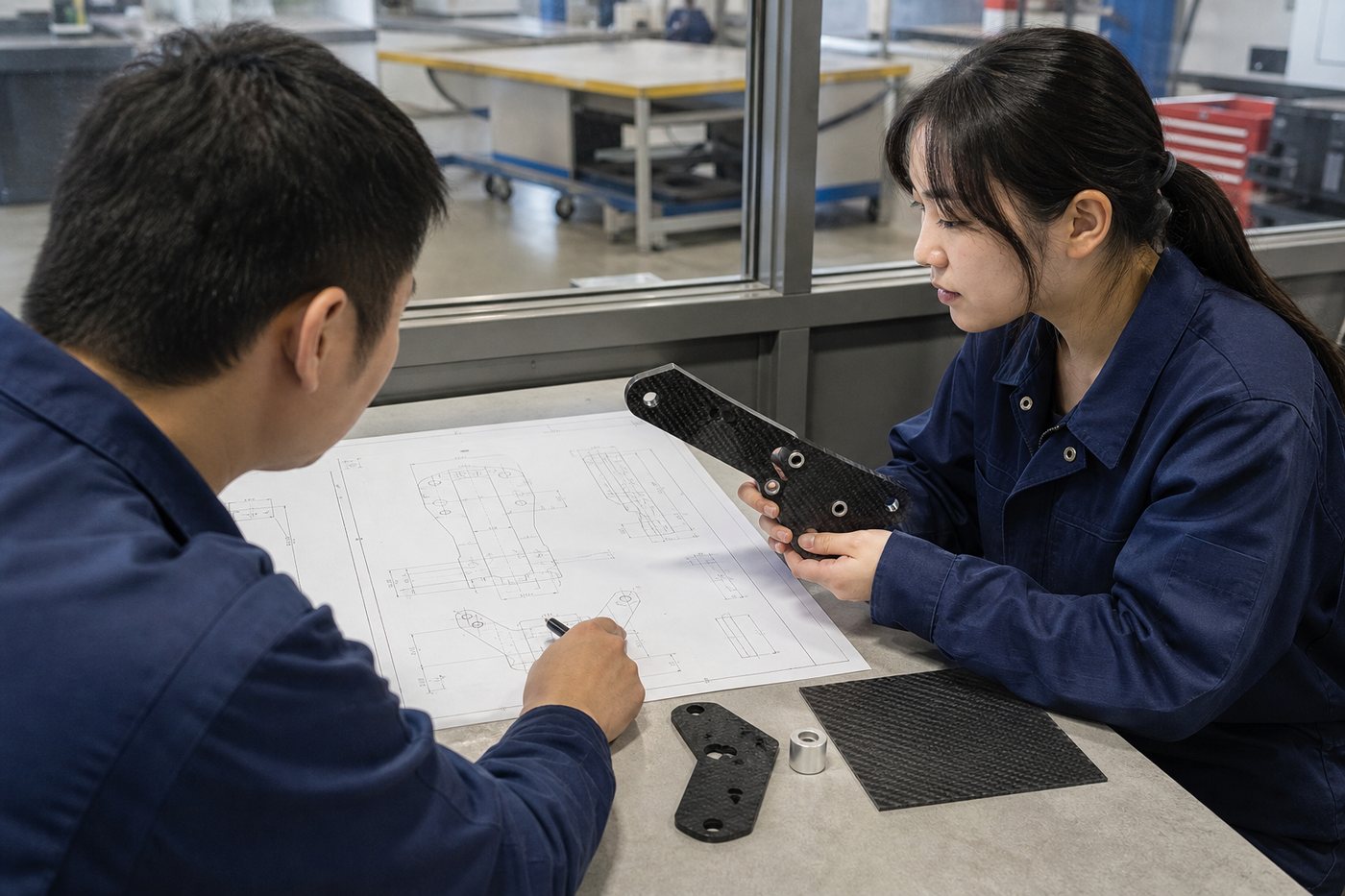
Build requirements around customer CAD, drawings, samples or application data
Process Selection
Match machining, pultrusion, tube production or molding to the geometry
Integrated Interfaces
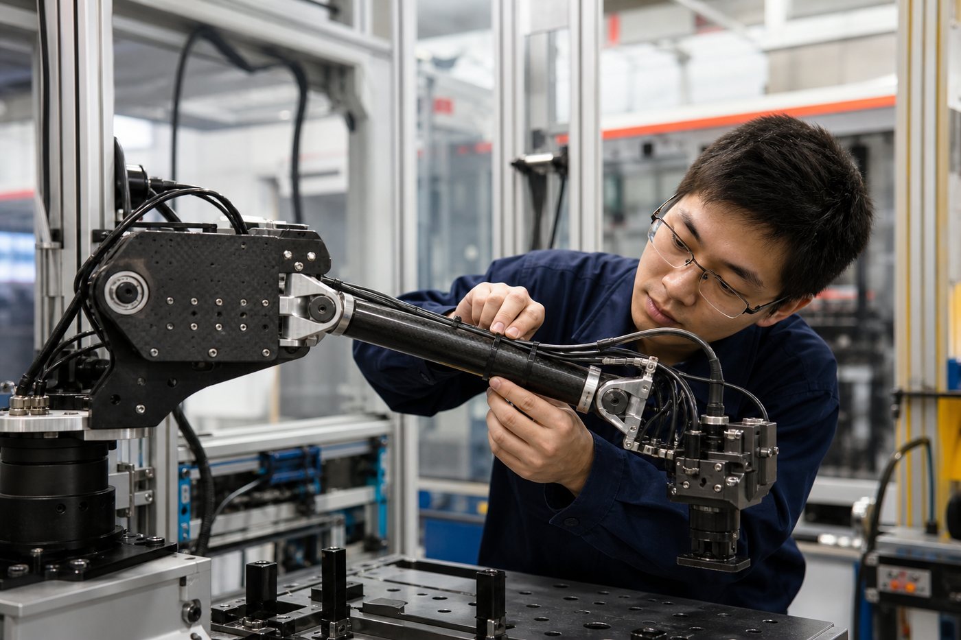
Review bonding, threaded inserts, fittings and final assembly
Prototype to OEM Supply
Support validation builds and controlled repeat production
CUSTOM PART TYPES
Custom Carbon Fiber Components We Manufacture
Different geometries require different materials, tooling and production routes. Final feasibility is confirmed during engineering review.
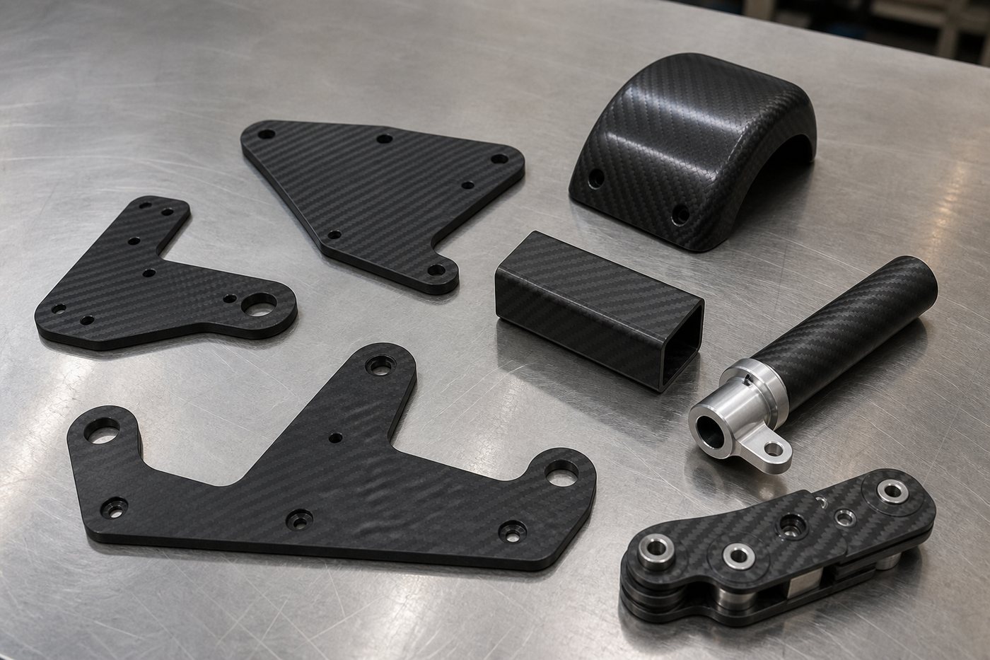
CNC Machined Parts
Brackets, plates and frames machined from carbon fiber sheet or laminate.
Molded CFRP Parts
Curved covers, shells and three-dimensional parts produced from dedicated tooling.
Custom Tubes
Round, square, rectangular and project-specific structural members.
Solid Rods & Profiles
Pultruded rods and constant-section profiles for structural applications.
Parts with Metal Inserts
Bonded interfaces reviewed around geometry, load and environment.
Composite Assemblies
CFRP components combined with fittings, hardware and subassembly work.
One Project, One Appropriate Manufacturing Route
A flat CNC bracket, a continuous structural profile and a molded three-dimensional cover should not be treated as the same product. Geometry, load direction, finish, quantity and tooling budget determine the practical route.
Custom Carbon Fiber Parts from CAD Files and Samples
Send a drawing, CAD file, sample part or application brief. The review aligns geometry with the laminate, process, interfaces, tolerances, environment and expected production quantity.
Geometry
Dimensions, datums, holes, radii and assembly interfaces.
Performance
Loads, stiffness, impact, fatigue and weight targets.
Environment
Temperature, chemicals, moisture, UV and electrical considerations.
Commercial Plan
Prototype quantity, annual demand, tooling and delivery target.
Choose the Right Carbon Fiber Manufacturing Process
The recommended route depends on shape, fiber direction, surface, tooling, production volume and commercial requirements.
Part Requirement
Process to Review
Typical Components
Flat 2D Geometry
Sheet laminate and CNC machining
Brackets, frames, mounting plates and panels
Constant Cross Section
Pultrusion
Rods, beams, channels and structural profiles
Round or Profiled Tube
Roll wrapping or project-specific tube process
Arms, struts, sleeves and lightweight shafts
Curved 3D Geometry
Prepreg or project-specific molding
Covers, shells, housings and shaped structural parts
Mechanical Interface
Bonding, metal inserts and assembly
Threaded joints, fittings and finished subassemblies
CUSTOMIZATION OPTIONS
Material, Laminate, Finish and Interface Options
Carbon Reinforcement
Fiber grade reviewed around target strength, stiffness and cost.
Fiber Architecture
Unidirectional, woven fabric or an engineered laminate schedule.
Resin & Environment
Resin system reviewed around heat, moisture and chemical exposure.
Surface Finish
Natural laminate, matte, gloss or project-specific coating.
Dimensions & Tolerance
Critical datums and criteria defined on the approved drawing.
Machined Features
Holes, pockets, chamfers, countersinks and trimmed contours.
Metal Interfaces
Bonded fittings, threaded inserts, bushings and mounting hardware.
Identification & Packing
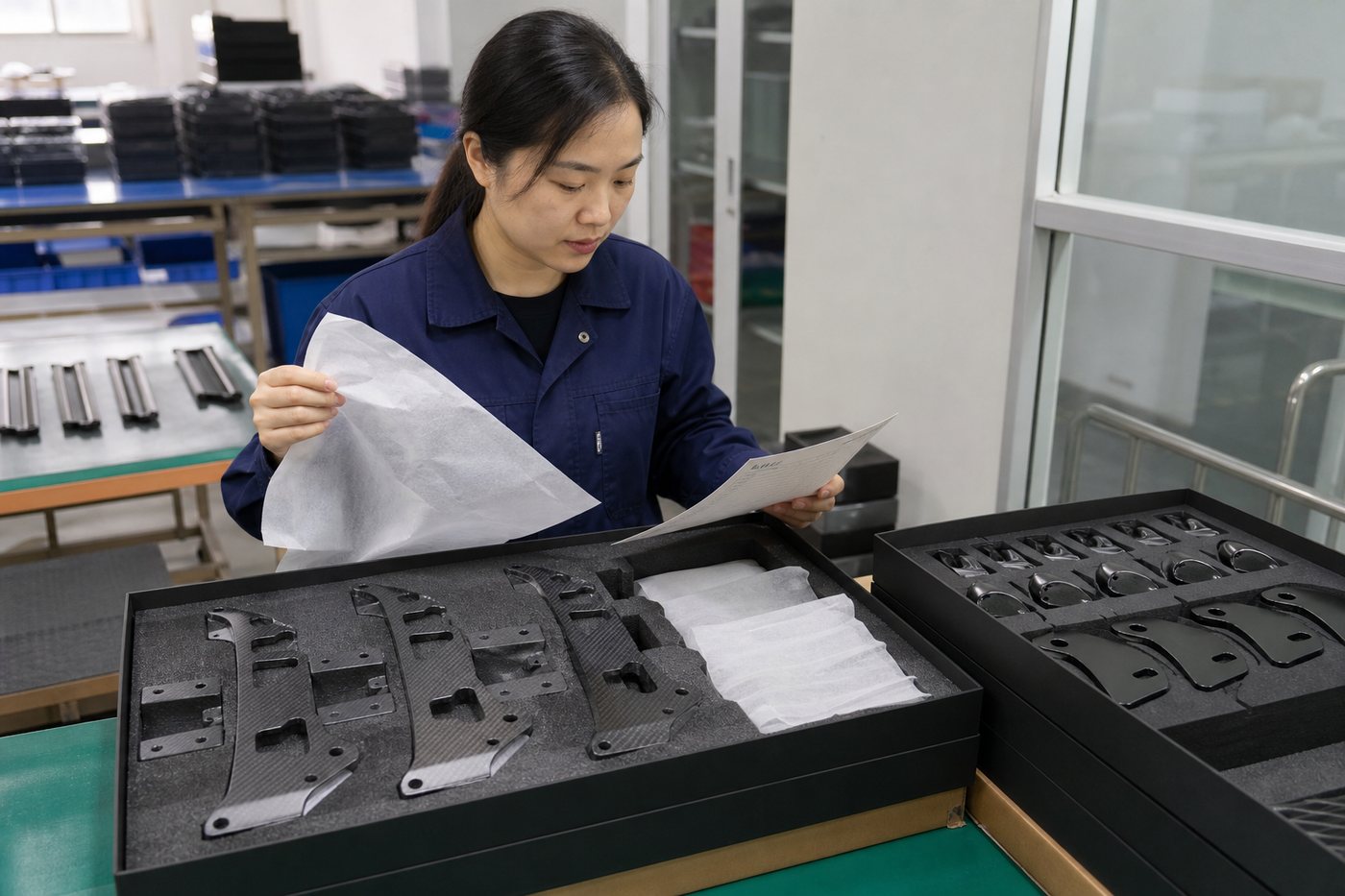
Part marking, batch control and protective packaging.
PROJECT WORKFLOW
From Requirement Review to OEM Production
Each project moves through a controlled technical and commercial review before repeat production.
01 · Requirements
Receive drawing, loads, environment, quantity and delivery target.
02 · DFM Review
Align geometry, laminate, process, tooling and inspection.
03 · Quotation
Confirm scope, tooling, prototype plan and assumptions.
04 · Tooling & Setup
Prepare molds, fixtures, programs and process documents.
05 · Prototype
Manufacture initial parts for dimensional and functional review.
06 · Approval
Freeze the drawing, process and acceptance criteria.
07 · Production
Run controlled batch manufacturing and inspection.
08 · Delivery
Protect, identify and pack parts for shipping.
SECONDARY PROCESSING
CNC Machined Carbon Fiber Parts
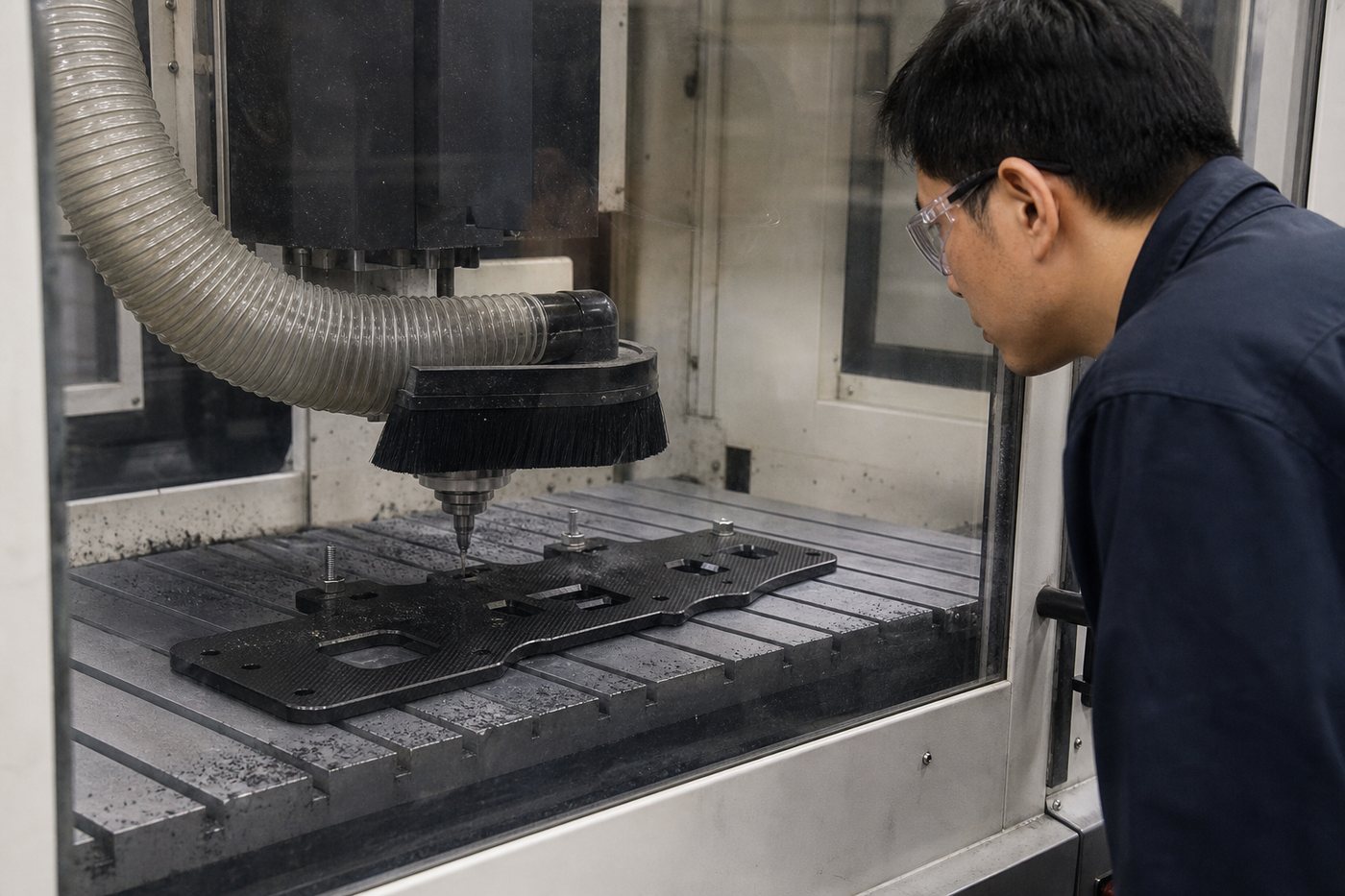
Flat and near-flat CFRP components can be cut and machined to the approved drawing. Tooling, workholding, edge distance and dust control are selected for composite processing.
CNC Routing
Outside contours, internal cutouts and repeatable nesting.
Drilling
Hole geometry reviewed around laminate and fastener loads.
Countersinking
Fastener seats controlled around laminate thickness.
Edge Finishing
Deburring, chamfering and edge sealing options.
MOLDED COMPONENTS
Custom Molded Carbon Fiber Parts
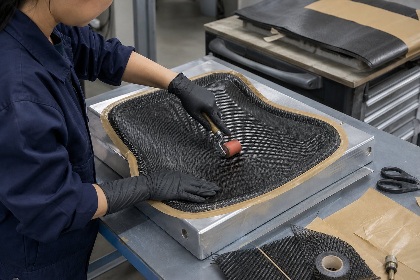
Curved covers, shells and three-dimensional parts require a dedicated laminate and tooling plan. Mold surface, draft, trim line, inserts, finish and quantity are reviewed together.
Structural load paths, fiber continuity and repeatability must be considered together with appearance.
BONDED INTERFACES
Carbon Fiber Parts with Metal Inserts
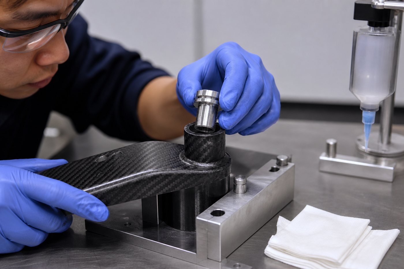
Machined aluminum, stainless steel or titanium interfaces can be bonded into compatible CFRP parts when bond area, insert geometry, loads, temperature and corrosion environment have been reviewed.
Threaded Inserts
Male or female threads carried by a compatible metal insert.
Bushings & Pivots
Local bearing and wear interfaces isolated from the laminate.
Bonded Fittings
End fittings and brackets with controlled preparation.
Custom components are developed around actual assembly loads and service environment, rather than a generic industry label.
Robotics
Low-mass arms, brackets and moving components.
Automation Equipment
Frames, supports, linkages and mounting parts.
UAV Structures
Lightweight plates, tubes and bonded assemblies.
Inspection Systems
Stable fixtures, supports and moving stages.
Industrial Machinery
Brackets, covers and structural members.
Optical Equipment
Low-mass rigid frames and positioning parts.
QUALITY & OEM SUPPLY
Inspection for Custom Carbon Fiber Components
Inspection points and acceptance criteria are established from the approved drawing, product risk and batch size. Certification and testing are provided only when included in the agreed project scope.
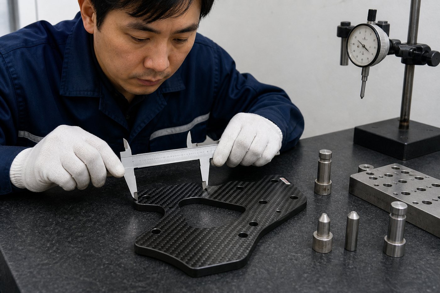
Dimensional Inspection
Critical dimensions, holes, datums and interfaces checked as specified.
Surface Review
Cosmetic and structural surfaces reviewed against agreed criteria.
Joint Validation
Bonded or inserted interfaces tested when required.
Batch Traceability
Part identification, records and protective packing planned for OEM supply.
FAQ
Custom Carbon Fiber Parts FAQ
Engineering, manufacturing and purchasing questions for made-to-drawing CFRP components.
Send your drawing or sample, application, loads, environment, dimensions, finish, interfaces, inspection requirements and quantity for a manufacturing review.