
Home › Custom Solutions › Custom Carbon Fiber Profiles
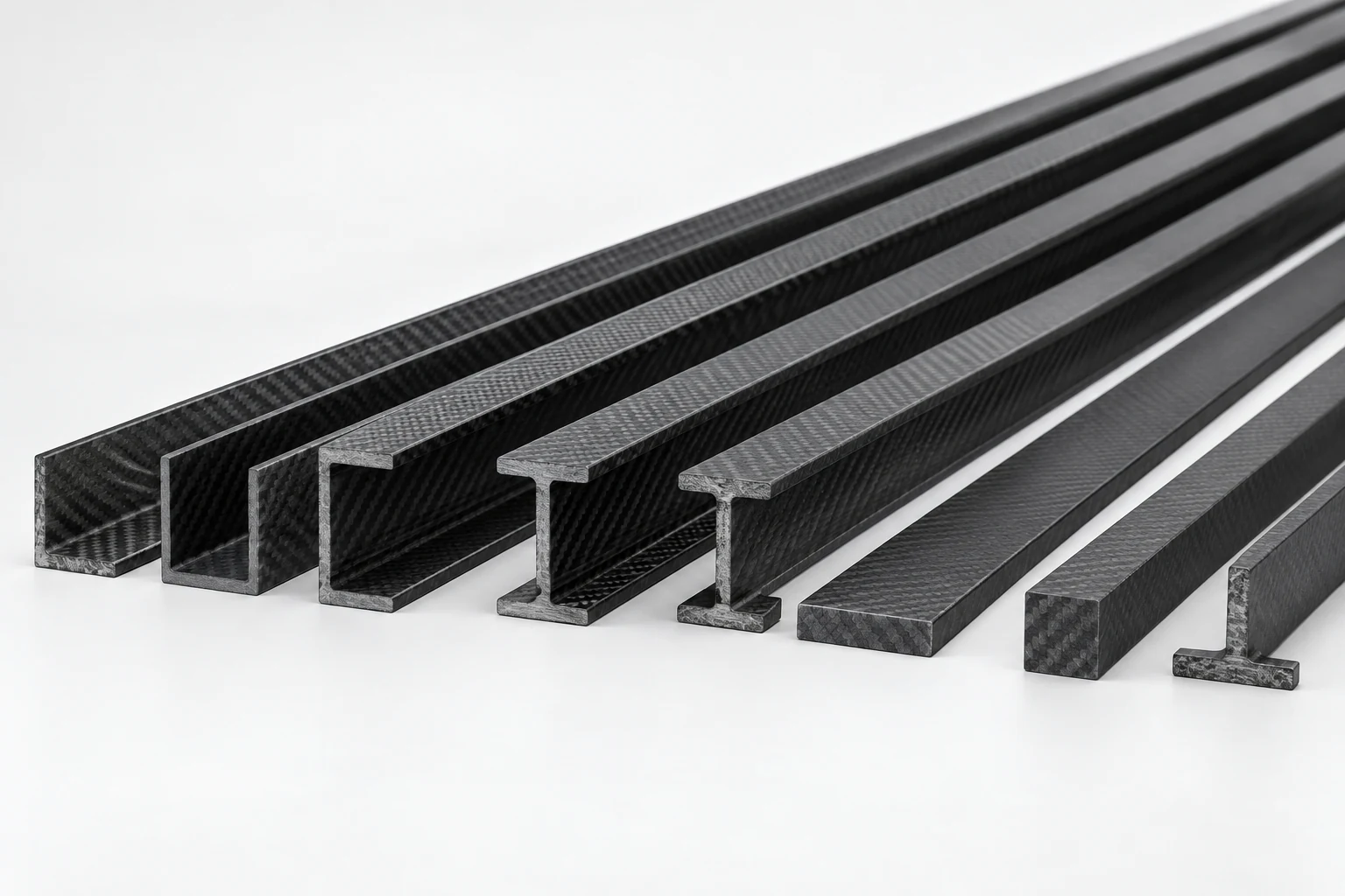
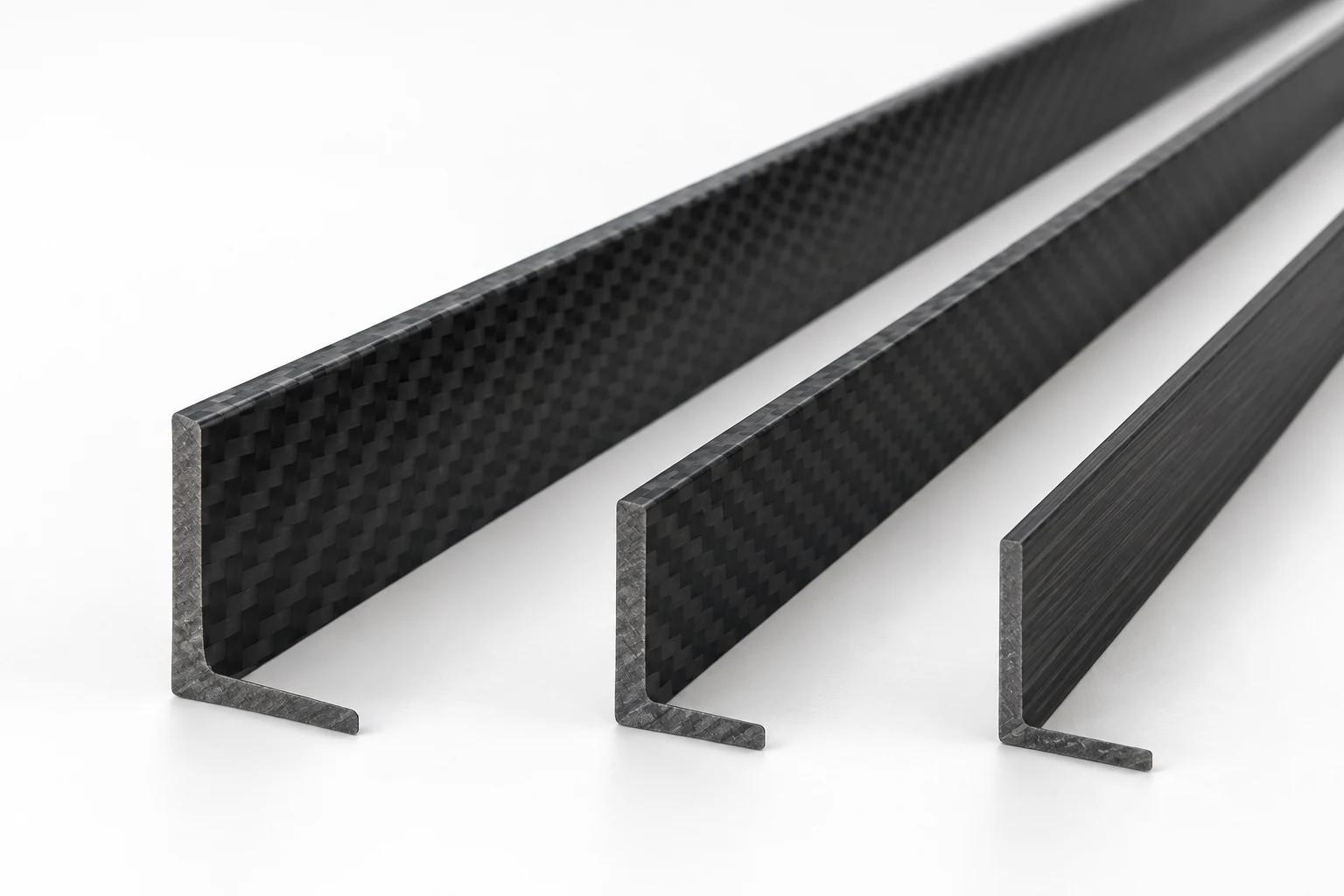
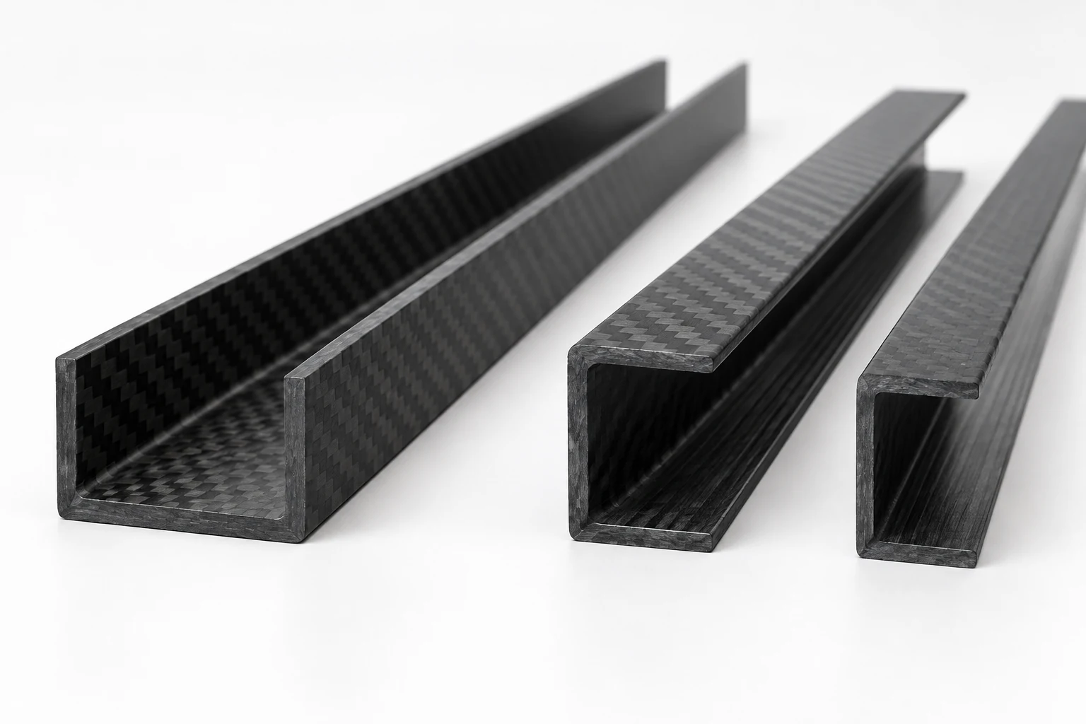
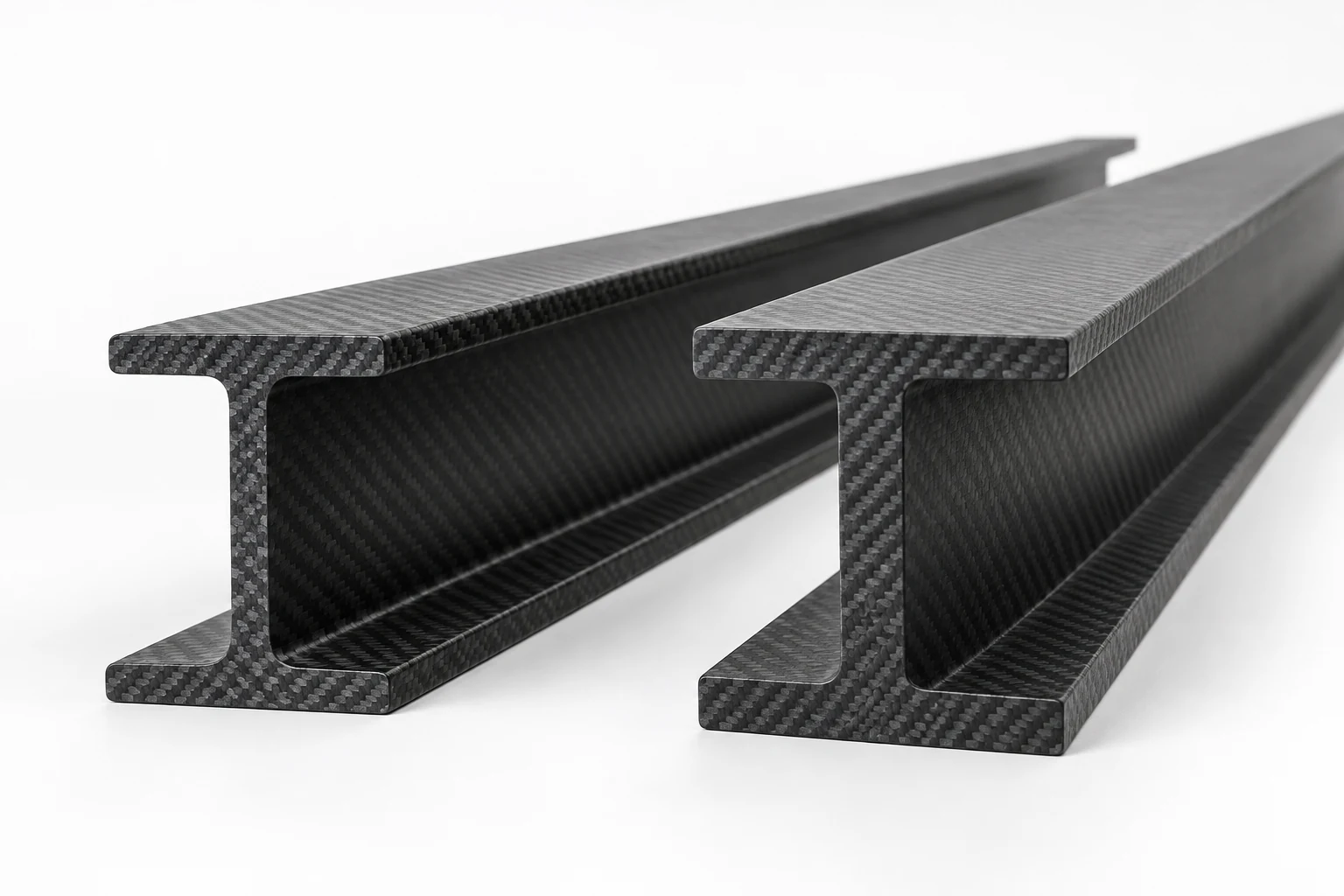
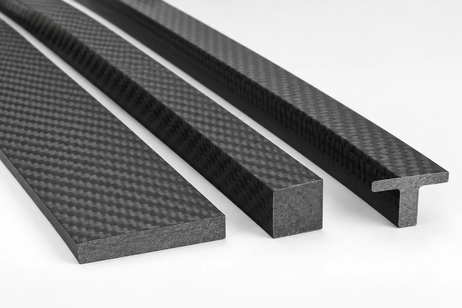
Images on this page are structural profile illustrations. Final geometry, surface and production method follow the approved project specification.
Custom Carbon Fiber Profiles
Custom carbon fiber profiles for lightweight frames, supports, guides and structural assemblies. We review L, U, C, I and H sections together with flat bars, square bars and special solid profiles from your section drawing, length and load direction.
Open Sections · Beam Profiles · Solid Bars · Custom Cross-Sections
| Profile families | L angles, U/C channels, I/H beams, flat and square bars |
|---|---|
| Production basis | Constant cross-section reviewed for pultrusion or another agreed process |
| Drawing inputs | Cross-section, length, quantity, load direction and machining |
| Secondary work | Cutting, drilling, slots and end details subject to drawing review |
Each section and size may require dedicated tooling. Send the full cross-section rather than only an outside width and height.
Profile Shapes Covered on This Page
This is one product-family page. The sections below are drawing-based options rather than a list of stocked sizes. A useful first inquiry identifies the section, overall dimensions, wall or web thickness, length and the faces that carry load or connect to other parts.
| L angle profile | Two legs at 90°. Used for corner reinforcement, edge supports, frame joints and panel connections. |
|---|---|
| U channel | A base with two side walls. Used for guides, cable paths, panel edges and equipment supports. |
| C channel | An open channel with one side opening, often selected for frame rails, mounting tracks and brackets. |
| I beam | A central web between upper and lower flanges for bending loads in a defined main direction. |
| H beam | A wide-flange beam form used where a broader connection face or frame member is needed. |
| Flat bar | A solid rectangular section for stiffeners, links, supports and machined connection pieces. |
| Square bar | A solid square section for frame members, locating elements and equipment structures. |
| Custom solid profile | T, trapezoid, keyed or customer-defined constant sections reviewed for tooling feasibility. |
Choose the Section from the Load Path
The profile name is only the starting point. The important question is where the section must resist bending, twisting, compression or local fastener loads. An L angle gives two connection faces but is asymmetric. U and C channels provide accessible mounting surfaces, while I and H sections place more material away from the neutral axis for bending in a chosen direction.
Open profiles need connection details
Show which leg, flange or web is clamped, bonded or drilled. Hole position, edge distance and washer or insert details affect the remaining load path. If two profiles meet at a corner, include the bracket, adhesive area or mechanical fastener arrangement rather than sending isolated section drawings.
Solid bars suit compact interfaces
Flat and square bars provide more material for local machining and bearing than thin open walls, but added section area also adds mass. Mark the zones that will be drilled, slotted or milled so the profile and secondary operations can be reviewed together.
Pultrusion, Tooling and Fiber Direction
Constant cross-sections are commonly evaluated for pultrusion. Continuous reinforcement is pulled through a forming and curing tool, which makes the profile direction the main fiber direction. The process is well suited to repeat lengths, but it also means the cross-section must remain constant along the part.
A new cross-section or size may require dedicated tooling. Inside radii, wall transitions, thickness balance and corner reinforcement influence whether the section can be produced consistently. Very abrupt thickness changes or sharp internal corners should be discussed before a production drawing is finalized.
Longitudinal stiffness is usually the first consideration, but transverse and torsional requirements still matter. State the real load directions and connection loads so the reinforcement concept can be reviewed instead of assuming the same response in every direction.
Dimension the Full Cross-Section
Provide a dimensioned section view. For open profiles, include leg or flange widths, web or base dimensions, wall thicknesses, inside and outside radii and any draft or taper that matters to fit. For solid profiles, define all faces, angles, keys and locating features.
Also state cut length, permissible bow or twist where assembly requires it, and the datum faces used for inspection. Avoid applying one tight tolerance to the entire drawing. Identify the dimensions that control mating, alignment or load transfer and assign practical requirements to those features.
Illustrative drawing note
Example: “Channel inside width controls the mating rail. Base-to-wall angle and cut length are inspection features. Drill pattern is located from the base datum after the profile is cut.” The final tolerance values should come from the project requirement and manufacturing review.
Secondary Cutting and Machining
Profiles can be reviewed with cut-to-length ends, holes, slots, notches, counterbores or other drawing-defined details. Show whether the feature is made before assembly and whether it locates another component. Tool access can be limited inside narrow channels or near a flange.
Machining interrupts continuous fibers, so closely spaced holes, sharp notches and small edge distances deserve review. Threaded connections may use through-bolts, bonded inserts or separate metal interfaces depending on the load and service needs. Do not assume that a thread cut directly into the composite will suit repeated assembly.
Specify edge finish and dust-sensitive cleanliness requirements on the drawing. If the profile will be bonded, mark the bonding faces and any surface-preparation requirements separately from cosmetic visible faces.
What to Send for a Profile Quotation
| Section drawing | Fully dimensioned L, U, C, I, H, bar or custom cross-section |
|---|---|
| Length | Finished cut length and any length-dependent straightness or twist requirement |
| Application | Frame, guide, support, beam, rail or other assembly function |
| Loads | Main bending, tension, compression, torsion and connection directions |
| Material requirements | Fiber orientation, resin or environmental requirements if already specified |
| Secondary operations | Cut ends, holes, slots, notches, inserts and identification |
| Quantity | Prototype need, first production batch and expected repeat demand |
| Inspection | Datum faces, mating dimensions and features that control assembly |
If no final section exists yet, send a sketch with the available installation envelope, connection faces and load direction. That is enough for an initial manufacturing review, but production still requires an approved drawing.
Carbon Fiber Profiles: Common Questions
This page covers drawing-based projects. Existing tooling and standard-size availability must be checked for the requested section, dimensions, length and quantity; the page does not promise that every illustrated shape is stocked.
Usually the cross-section controls the tooling. A change in leg width, wall thickness, flange geometry or another section dimension may require different tooling, so send each required size for review.
Both are open profiles. A U channel is usually described as a base with two side walls; a C channel is oriented and used as a side-opening structural channel. The dimensioned drawing, rather than the letter alone, defines the actual part.
Secondary machining can be reviewed from the finished-part drawing. Feature position, edge distance, tool access and the local load path all affect feasibility.
A constant custom section such as a T, trapezoid or keyed profile can be evaluated. Tooling, section transitions, quantity and material requirements must be reviewed before production is confirmed.
Send the Cross-Section Drawing
Send the profile section, finished length, quantity, load direction and secondary machining. Point out the surfaces that mate, bond or receive fasteners. We will review the section and identify the information needed for tooling and production planning.
For closed hollow sections, see our carbon fiber tube options. For drawing-based plates and brackets, see custom carbon fiber parts.