
Home › CNC Machined Parts › Carbon Fiber Drone Frame Parts


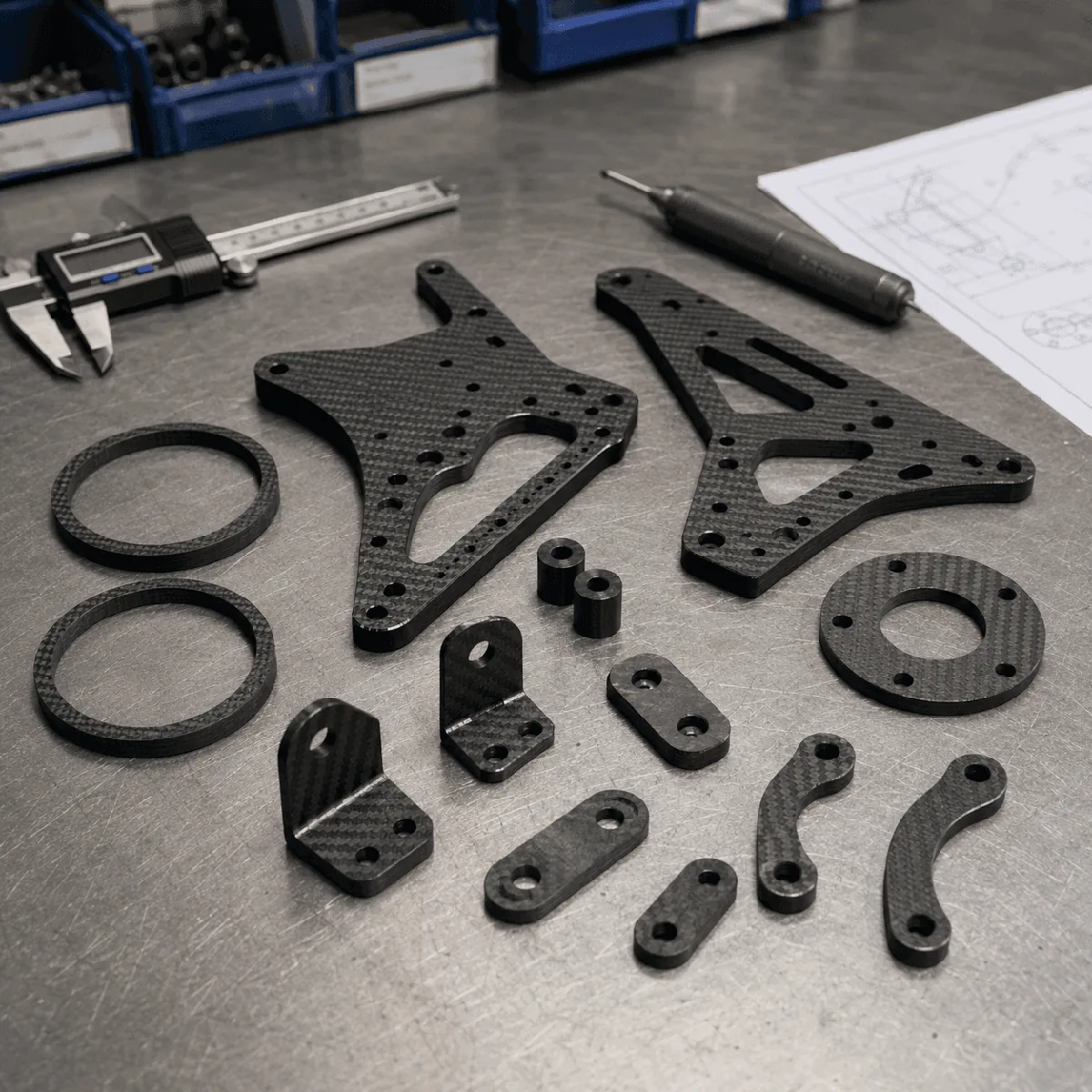
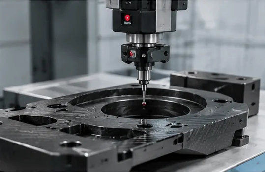
Product examples show typical CNC-cut drone components. Final geometry follows the approved customer drawing.
Carbon Fiber Drone Frame Parts
Carbon fiber drone frame parts CNC-cut from plate for FPV, multirotor and custom UAV structures. Send the frame drawing, plate thickness, hole pattern and quantity so we can review the parts as an assembly rather than as isolated profiles.
Frame Plates · Replaceable Arms · Motor & Payload Mounts
| Parts | Center plates, arms, motor mounts, trays and brackets |
|---|---|
| Input | DXF or CAD files plus a dimensioned drawing |
| Options | Thickness, laminate, finish, edge and marking requirements |
| Supply | Prototype sets and drawing-based OEM batches |
Include the mating hardware and stack layout when hole position or plate spacing is critical.
Drone Frame Parts We Can Machine
The page covers flat and 2.5D components machined from carbon fiber plate. A typical order may include the complete plate set or only the replaceable parts that receive the most wear.
Center & Cover Plates
Top plates, bottom plates, center plates and electronics decks with stack holes, cable windows and weight-relief cutouts.
Arms & Motor Interfaces
Individual arms, arm clamps and motor mount plates. The drawing should identify the motor pattern, fastener size and propeller clearance.
Equipment Mounts
Battery trays, camera plates, gimbal decks, antenna brackets, payload plates and landing-gear interfaces made to the system layout.
Start with the Frame Assembly, Not Just the Outline
A DXF profile shows where to cut, but it does not explain how the frame goes together. Include an assembly view or a simple stack diagram when several plates share standoffs, clamps or locating features. This lets us check whether the same datum controls related hole patterns and whether tools can reach the fasteners.
Define the interfaces
Mark the flight-controller stack, motor pattern, camera width, battery restraint, payload centerline and tube or landing-gear connections. If an arm must be replaceable, show the clamped length and the fasteners that transfer load into the center section.
Separate critical and noncritical dimensions
Identify the hole spacing and mating edges that control assembly. General outside contours and cosmetic openings often do not need the same tolerance as a motor pattern or a locating slot. A clear tolerance scheme is more useful than applying one tight value to every dimension.
Plate, Laminate & Fiber Direction
Plate thickness alone does not define the behavior of a drone arm or frame deck. The laminate construction and fiber directions determine how stiffness is distributed. Tell us where bending and twisting are expected, which faces are visible and whether the part is being matched to an existing plate.
For long arms and narrow links, the relation between the fiber direction and the part axis matters. Large slots, sharp internal corners and closely spaced holes interrupt the load path. Those details should be reviewed before the drawing is released for production.
If you are still choosing material, see the carbon fiber sheet thickness guide and the explanation of weave appearance and laminate direction.
CNC Details That Affect Fit and Service Life
Holes, slots and edge distance
Provide finished hole sizes and state which holes locate the assembly. Holes placed too close to an edge or to another cutout leave less laminate around the fastener. Add practical internal radii to slots and windows instead of drawing perfectly sharp corners that a rotary cutter cannot reproduce.
Countersinks and clamping
Call out countersinks only where a flush head is actually needed. The remaining laminate under the screw head must be considered, especially on thin plates. Repeatedly removed fasteners may need a through-bolt, insert or separate metal interface rather than a thread cut directly into the laminate.
Edge finish and identification
State whether edges require a simple break, chamfer or another agreed finish. Part numbers, orientation marks and matched-set identification can be added when they help assembly, but their location should avoid highly stressed areas and critical mating surfaces.
What to Include in Your RFQ
| CAD data | DXF or other agreed file for profiles; assembly model where useful |
|---|---|
| Drawing | Units, revision, datums, critical dimensions and tolerances |
| Material | Plate thickness, laminate requirement and visible surface |
| Frame layout | Motor pattern, stack spacing, arm joints and mating hardware |
| Machining | Holes, slots, countersinks, chamfers and marking |
| Quantity | Prototype sets, first batch and expected repeat demand |
| Inspection | Critical hole spacing, outside profile, thickness and fit checks |
| Delivery scope | Loose parts, matched sets or agreed subassembly |
Example drawing note
Illustrative example: “Motor-mount hole pattern and arm-to-center locating holes are critical; outside arm profile uses the general drawing tolerance. Deburr cut edges without changing the locating faces.” This type of note tells the machinist what controls fit without pretending every contour has the same function.
Prototype and Batch Checks
The first set should be checked as an assembly. Confirm the motor holes, center stack, plate spacing, cable access and arm replacement before approving a batch. If the design changes, keep the drawing revision and CAD file synchronized so old and new parts are not mixed.
For production orders, agree which dimensions will be recorded and whether parts are packed as complete frame sets or by part number. Visual inspection should cover cut edges, surface damage and obvious machining defects; dimensional checks should follow the critical features identified on the drawing.
Carbon Fiber Drone Frame Parts: Common Questions
Yes, a drawing-based set can include center plates, arms, motor mounts, equipment plates and smaller brackets. Send the assembly layout as well as the individual profiles so shared interfaces can be reviewed.
A DXF or another agreed profile file is useful for cutting, but it should be accompanied by a dimensioned drawing showing units, thickness, revision, critical hole patterns and tolerances.
A sample, photographs and measurements can support an initial review. A controlled drawing is still preferable when the new arm must interchange with an existing frame or be reordered later.
These features can be reviewed when they are shown on the drawing. Specify the fastener, side of the plate and required finish; countersinks need particular care on thin laminates.
This page covers carbon fiber structural parts made to the customer’s approved design. Complete aircraft integration, flight control and flight validation are separate responsibilities unless they are explicitly included in an agreed project scope.
Send Your Drone Frame Drawing
Send the frame files, plate thickness, quantity and a short note on the application. Point out the interfaces that control motor alignment, plate stacking and arm replacement. We will review the machining scope and the information needed for a quotation.
For other plate-based components, see our custom carbon fiber parts capability.