
Home › Carbon Fiber Rods › Carbon Fiber Push Rods


LIGHTWEIGHT LINKAGE ASSEMBLIES BUILT FROM THE INTERFACES INWARD
Custom Carbon Fiber Push Rods and Linkage Assemblies
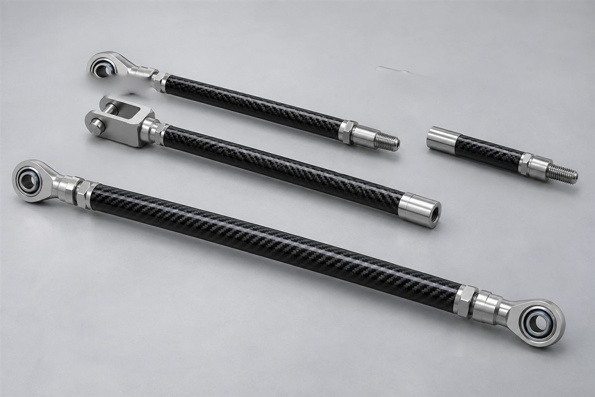
Carbosources develops custom carbon fiber push rods and linkage assemblies for OEM projects that need low moving mass, axial stiffness and drawing-controlled end interfaces. A finished push rod is more than a cut carbon rod. The carbon member, bonded metal inserts, threads, locknuts, rod ends or clevises must work as one load path.
This page covers carbon fiber push rods for robotics, UAV control systems, automation equipment, lightweight machinery and similar linkage applications. Send the installed length, tension and compression loads, end-fitting geometry, required adjustment and service environment. These inputs allow the rod, joint and inspection plan to be reviewed together before quotation.
| Design input | What the RFQ or drawing should define |
|---|---|
| Functional length | Pin-center, shoulder-to-shoulder or end-face length, including the adjustment position |
| Carbon member | Solid rod or tube, outside diameter, inside diameter, length and construction requirement |
| Loads | Maximum tension, maximum compression, side load, vibration, impact and duty cycle |
| End interfaces | Male or female threads, rod ends, clevises, ball joints or customer-supplied hardware |
| Adjustment | Fixed length, single-end adjustment, opposite-hand threads or required adjustment range |
| Alignment | Concentricity, straightness, runout and angular relationship between both ends |
| Environment | Operating temperature, moisture, chemicals, outdoor exposure and maintenance access |
| Qualification | Critical dimensions, proof load, pull-out test, fatigue expectation and sample plan |
A useful request identifies the complete linkage function. “Make it as light as possible” does not define stiffness, buckling resistance or joint reliability. State what the push rod connects, how the load enters each end, the unsupported length and the allowable deflection or positional error. Carbosources can then review feasible construction and interface options without treating a material name as a performance specification.
Define the Load Case Before Choosing the Rod
Begin with the load direction. A short linkage carrying mainly tension behaves differently from a long member that reverses between tension and compression. Compression introduces a buckling limit that depends on unsupported length, end restraint and bending stiffness. A small transverse offset can also introduce bending even when the nominal requirement is axial.
Define the installed geometry at the working adjustment position. Pin-center length is usually more useful than carbon-tube length because threaded fittings, rod ends and locknuts change the finished dimension. If the linkage moves through an arc, provide the articulation angle and surrounding clearance so the selected end hardware does not bind.
The carbon member may be a solid pultruded rod, a hollow tube or another reviewed construction. Pultruded material is efficient when the primary demand is longitudinal stiffness, while a tube can provide useful section stiffness at lower mass for longer members. Torque, off-axis load, local clamping and visible surface requirements may change the appropriate construction. For raw material options, review the carbon fiber rods range and the pultruded carbon fiber rods page.
Design the Threaded Ends and Bonded Inserts
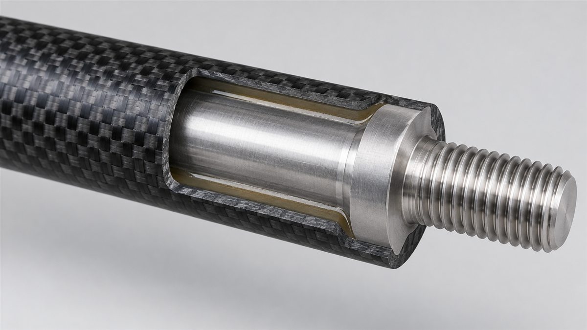
Threads are normally carried by a metal fitting rather than cut into a thin composite wall. A bonded insert for a carbon fiber pushrod should be defined by its material, insertion length, bond diameter, shoulder geometry, adhesive gap and load-transfer path. The tube bore and insert diameter must provide a controlled fit without forcing the laminate outward.
Aluminum can reduce fitting mass; stainless steel may be selected where thread durability or environmental resistance is more important; other materials require project review. The joint also needs a way to resist service torque when locknuts or rod ends are adjusted. Surface preparation, fixture control and cure conditions are part of the manufacturing plan, not details to leave until final assembly.
| End configuration | Useful when | Drawing points to define |
|---|---|---|
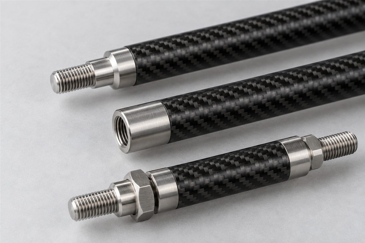
| Male threaded stud | A standard female rod end or clevis will be installed | Thread size, hand, engagement, locking and shoulder position |
| Female threaded insert | Interchangeable male hardware is required | Thread depth, bottom clearance, torque and corrosion environment |
| Spherical rod end | The linkage needs angular misalignment capability | Bore, articulation, width, pin size and installed orientation |
| Clevis end | A pinned fork connection is preferred | Gap, pin diameter, edge clearance and fork orientation |
| Opposite-hand threads | Length must be adjusted without disconnecting the linkage | Left/right identification, adjustment range and locknut access |
Specify whether Carbosources supplies the complete hardware, bonds customer-supplied fittings or prepares the carbon member for assembly elsewhere. A photo can communicate the concept, but the released drawing must control every interface.
Control Buckling, Alignment and Joint Loads
Long, slender carbon fiber linkage rods can fail by instability before the material reaches its nominal compressive strength. The review therefore needs unsupported length, end conditions and the highest compressive load. Adding diameter may improve buckling resistance more efficiently than making a small rod solid, but available space and joint geometry set practical limits.
The insert region is another critical area. A short stiff insert can transfer load abruptly into the composite, while an excessive press fit can split a tube end. Side load from a misaligned rod end can combine bending with axial load. Possible design responses include a longer load-transfer region, local end reinforcement, a better-supported fitting or a joint that provides the required articulation.
Adjustment features must remain measurable. Show the nominal thread engagement and the minimum safe engagement at both ends of the adjustment range. If left-hand and right-hand threads are used, identify them visibly on the drawing and define how the finished assembly is locked. For fixed-length carbon fiber control rods, dimension the functional centers and the allowed angular orientation between clevises or rod ends.
Do not apply installation torque through an unsupported carbon tube. Define wrench flats, locknut access and the approved holding point on the fitting. If the assembly requires repeated service, state the expected adjustment frequency and whether end hardware is replaceable.
What to Put on a Push Rod Drawing
- Installed length: pin centers, end faces or shoulders at the nominal adjustment position.
- Carbon geometry: solid or hollow construction, outside diameter, inside diameter and usable length.
- Load case: tension, compression, transverse load, reversals, vibration and duty cycle.
- Hardware: rod-end or clevis drawings, thread size and hand, materials and supplied components.
- Adjustment: required range, minimum thread engagement, locknuts and accessible wrench flats.
- Datums: centerline, end faces, pin centers and angular orientation between fittings.
- Environment: temperature, moisture, chemicals, UV exposure and maintenance conditions.
- Acceptance: straightness, runout, functional length, bond appearance and requested tests.
Provide a dimensioned PDF with the drawing revision. STEP or IGES is useful for machined inserts, clevises and surrounding assemblies; DXF can support two-dimensional profiles. Identify critical dimensions rather than assigning tight tolerances to every feature. The tolerance should reflect the function, measurement method and repeatability needed at assembly.
If the carbon member is bought separately, link it to the controlled hardware drawing and assembly procedure. If a complete ready-to-install linkage is required, include the mating geometry and packaging constraints. Related options include carbon fiber threaded rods and CNC-machined carbon fiber parts.
Inspection and Qualification Planning
Inspection begins with the functional dimensions. Typical checks can include overall or pin-center length, thread engagement, fitting clocking, straightness, runout, rod-end freedom and visible bond-line condition. The approved drawing should state the datum setup and acceptance values instead of relying on a generic “high precision” note.
Where the application requires qualification, define the test before prototypes are built. A pull-out test evaluates a different failure mode from an axial proof load, compression test or cyclic durability test. State the direction, fixture, load level, hold time, number of samples and whether the tested parts remain usable. Carbosources reviews requested inspection and testing against the agreed design; no universal load rating applies to every push rod.
Typical uses include UAV and model-aircraft control linkages, robotic mechanisms, delta-style motion systems, packaging and textile machinery, inspection equipment and other lightweight reciprocating assemblies. Application names are starting points only. Each project still needs its actual load, geometry, interfaces and service environment.
This product scope covers custom linkage and control assemblies. Engine valve-train push rods and safety-critical vehicle suspension members involve specialized temperature, lubrication, fatigue and validation requirements and should only be quoted through a separate confirmed engineering review.
Send Your Carbon Fiber Push Rod Requirements
Send the assembly drawing, installed length, carbon member dimensions, end-fitting details, tension and compression loads, quantity, environment and requested inspection. Carbosources will review the rod, bonded inserts, hardware, adjustment and fixture requirements before quotation.
Frequently Asked Questions
Can you supply carbon fiber push rods with threaded ends?
Threaded metal inserts and matching end hardware can be reviewed from the drawing. Specify thread size and hand, insertion geometry, adjustment range, locking method and load case.
Should the carbon member be solid or hollow?
The choice depends on length, buckling, bending stiffness, mass, available diameter and interface design. Provide the load and envelope rather than selecting from diameter alone.
Can rod ends or clevises be included?
Complete assemblies can be reviewed when the hardware specification, orientation, mating pin geometry and sourcing responsibility are defined.
How should an adjustable push rod be dimensioned?
State the functional length at nominal adjustment, total adjustment range, minimum thread engagement and the location of locknuts or wrench flats.
What information is needed for a quote?
Provide the released or preliminary drawing, application, loads, installed length, carbon geometry, fittings, quantity, service environment, tolerances and requested qualification tests.