
Home › Carbon Fiber Tubes › Carbon Fiber Telescopic Tubes

CUSTOM NESTED CFRP TUBE SETS
Custom Carbon Fiber Telescopic Tubes
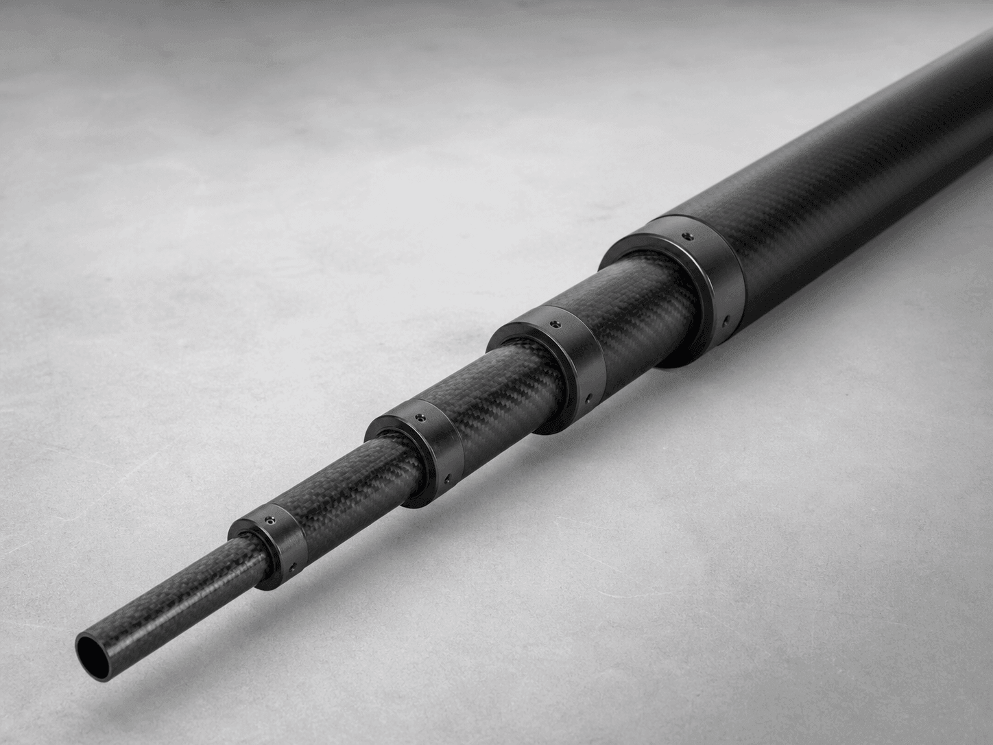
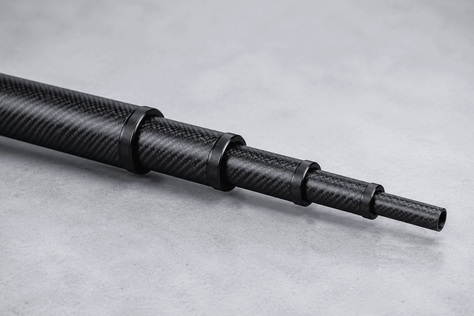
Carbosources supplies custom carbon fiber telescopic tube sets for lightweight extendable structures. These telescoping carbon fiber tubes are reviewed as a matched assembly: section diameters, overlap, clearance, extended length, collapsed length and connection details must work together.
Send the assembly drawing, required reach, working load direction and locking concept so each telescopic carbon tube section can be evaluated for fit and manufacture.
| Design input | What to specify |
|---|---|
| Length | Collapsed length, extended length and usable travel |
| Sections | Number of stages and the nesting sequence |
| Tube geometry | Outside diameter, inside diameter or wall thickness for every section |
| Overlap | Minimum engaged length at each operating position |
| Interfaces | Clamp, twist lock, button, insert, bonded joint or machined end features |
| Finish | Visible weave, matte or gloss requirements, subject to process review |
Include mating hardware and the assembled operating positions. A list of separate tube diameters is not enough to verify sliding fit, overlap or load transfer.
Define the Extended and Collapsed Lengths
Define the shortest stored length and the maximum working length on the same assembly drawing. State whether the quoted extended length includes end fittings, handles, clamps or mounting hardware. The usable travel is the difference between operating positions after the required overlap is retained.
For long-reach equipment, show where the load acts and whether the tube is used horizontally, vertically or at changing angles. Bending, torsion and local clamp pressure can control the laminate and joint design. The carbon fiber tube sizing guide explains why diameter and wall thickness should be considered together.
Design the Nesting Sequence and Sliding Fit
Each section needs a controlled relationship with the next section. Specify whether dimensions are nominal, finished or interface-critical. Clearance must allow smooth extension without excessive movement, while the overlap must remain sufficient for alignment and load transfer.
Also identify the surfaces that slide, the areas that may be bonded and any locations that require machining. Finish build-up, local reinforcement and dimensional variation can affect nesting. Critical fits should be called out separately from general tube dimensions and reviewed with the tube tolerance guidance.
Locking, Anti-Rotation and End Interfaces
Show the chosen locking concept and the forces it introduces into the tube. Clamp collars, twist locks, spring buttons and mechanical stops load the laminate differently. If the locking components are supplied by another manufacturer, include their drawings and installation requirements.
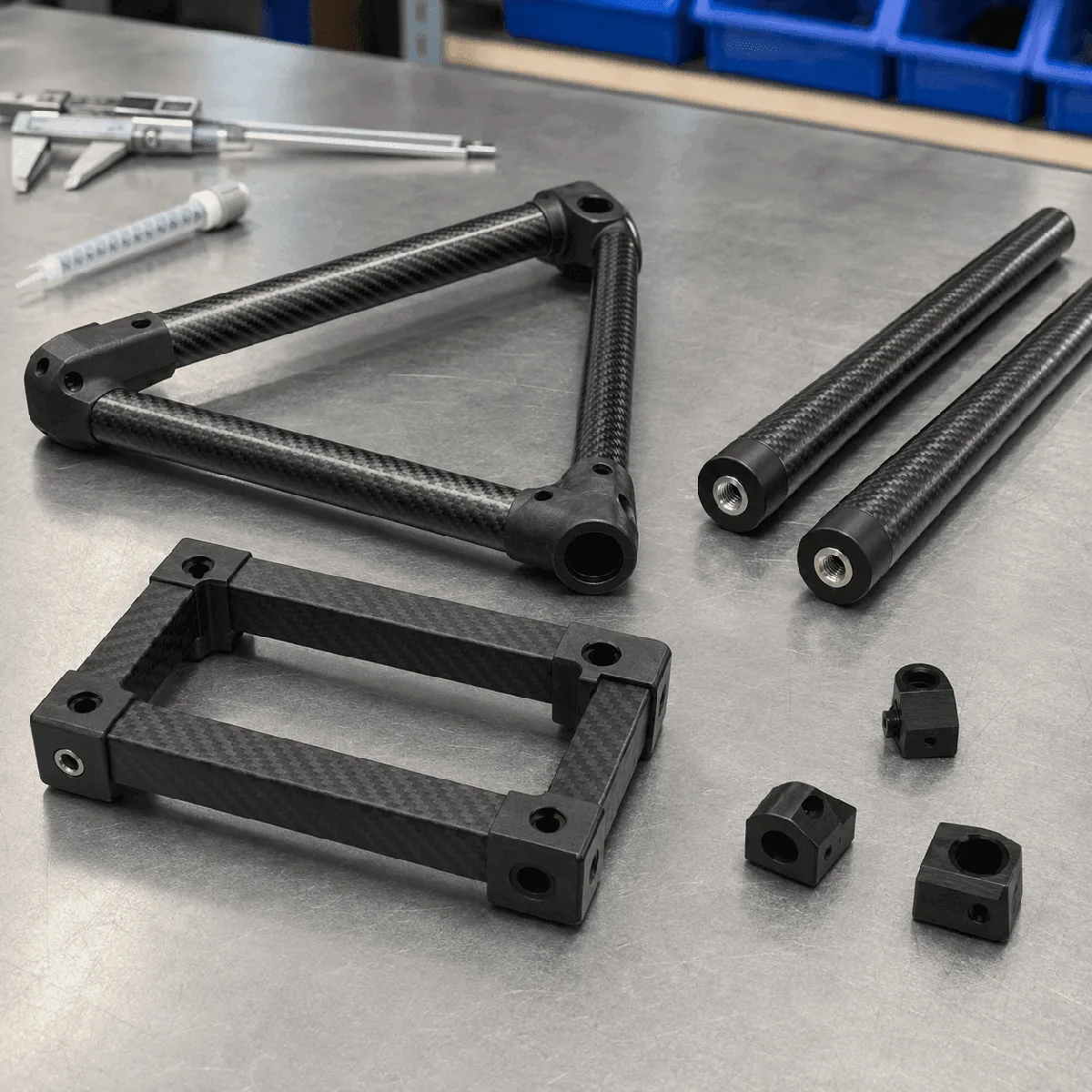
End features may include bonded inserts, threaded adapters, machined slots, cross holes or mounting faces. Locate these features from stable datums and identify the minimum distance from a cut edge. Our carbon fiber CNC machining page covers drawing details for holes, slots and finished interfaces.
What We Need to Review Telescoping Carbon Fiber Tubes
- Assembly drawing: extended and collapsed positions, stage order, overlap and mating hardware.
- Section schedule: OD, ID or wall thickness, cut length and quantity for every tube.
- Loading: direction and magnitude of bending, axial, torsional and local clamping loads.
- Interfaces: locks, stops, inserts, handles, clamps and bonded or fastened joints.
- Acceptance: critical fit dimensions, visible finish, inspection method and sample approval needs.
If the design is still developing, send the required reach, storage envelope, payload position and preferred number of stages. We can review whether the nesting sequence and manufacturing approach are practical before the final drawing is released. Tooling, MOQ and lead time are confirmed only after that review.
Inspection Points for a Telescopic Carbon Tube Assembly
Inspection should confirm the dimensions that control assembly: section OD and ID, straightness, cut length, overlap position, stop location and the fit between adjoining stages. The tube set should extend and retract through the agreed range without binding under the inspection setup defined for the project.
For repeat production, keep the approved tube schedule, assembly drawing and sample reference under revision control. A change to surface finish, lock hardware, adhesive thickness or machined interface can alter the fit even when the nominal tube diameter does not change.
Send Your Telescopic Tube Assembly Drawing
Send the assembly drawing, collapsed and extended lengths, tube schedule, locking concept, quantity and application. Carbosources will review the nesting arrangement, laminate requirements, machining and inspection points before quotation.