Carbon Fiber Tube Tolerances: What Engineers Should Specify Before Ordering
Carbon fiber tube tolerances affect fit, alignment, bonding, machining and inspection—but a tighter number is not automatically a better specification. The right tolerance depends on the tube geometry, laminate, manufacturing route, length, surface condition and the feature that actually controls the assembly.
This guide explains how engineers and OEM buyers can define practical dimensional requirements before requesting custom carbon fiber tubes.
Important: the values on a drawing should be reviewed against the actual manufacturing process. Carbosources confirms achievable tolerances after evaluating the complete specification.
Control the Interface
Apply tight tolerances to functional fits, datums and joining surfaces—not automatically to every dimension.
Name the Measurement
Define how, where and at what condition a dimension, wall or straightness requirement will be checked.
Match the Process
Pultruded, roll-wrapped and molded profiles do not create the same dimensional behavior or surface condition.
Agree Before Tooling
Resolve critical dimensions, inspection methods and acceptance criteria during quotation and drawing review.
Why Carbon Fiber Tube Tolerances Need Application Context
Metal-tube drawings are often reused for composite components without reconsidering how the part is made. That can create unnecessary cost or an inspection requirement that does not describe the real function. A carbon fiber tube is a cured laminate: fiber orientation, resin, compaction, mandrel or die condition, cure cycle, trimming and secondary machining all influence the finished geometry.
Begin by identifying what mates with the tube. A bearing seat may need a controlled local outside diameter. A bonded insert may depend more on the adhesive gap and prepared surface than on the full-length internal diameter. A telescoping assembly may require profile consistency and straightness over a working length. These are different requirements and should not be reduced to one blanket tolerance.
Fit
Which component slides, clamps, bonds or locates against the tube?
Datum
Which surface or axis establishes the measurement reference?
Gauge Length
Over what length must straightness, twist or profile be controlled?
Acceptance
What instrument, fixture or sample approval will determine conformity?
The Carbon Fiber Tube Dimensions to Put on the Drawing
A useful drawing separates nominal geometry from critical characteristics. It also states whether dimensions apply to an as-molded surface, a coated surface or a machined feature. The following items form a practical carbon fiber tube tolerance checklist.
| Characteristic | How to Specify It | Why It Matters |
|---|---|---|
| Outside dimension | OD, width, flat-to-flat or other controlled profile dimension | Clamps, bearings, guides and assembly clearance |
| Inside dimension | ID or internal profile, including any local fit zone | Insert, sleeve, mandrel or telescoping fit |
| Wall thickness | Nominal wall plus an agreed measurement method and locations | Mass, stiffness, local machining and bond geometry |
| Length and end squareness | Cut length, datum and perpendicularity requirement | Stack-up, bonding gaps and fixture alignment |
| Straightness | Maximum deviation over a stated gauge length | Linear motion, long-span alignment and rotating assemblies |
| Roundness or profile form | Circularity, flatness or profile tolerance tied to a datum scheme | Uniform contact and predictable assembly |
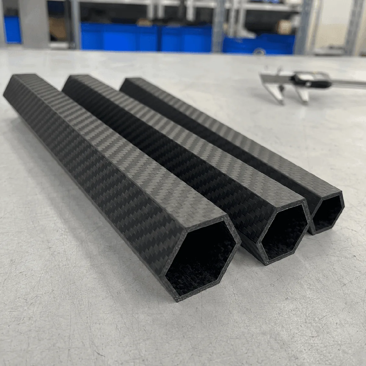
For square, rectangular and hexagonal profiles, define the dimension convention explicitly—for example outside width, inside width, flat-to-flat distance, corner radius and twist. For round tubes, specify whether the design is controlled by OD, ID, wall thickness or a functional fit. Avoid creating a closed tolerance loop in which OD, ID and wall thickness are all tightly controlled without identifying the priority.
How Manufacturing Method Changes Practical Tolerances
Pultrusion is well suited to continuous constant profiles and strong axial reinforcement. Die condition, pulling behavior, cure and profile geometry influence outside dimensions and straightness. Internal surfaces may not be the best choice for a highly controlled precision fit unless the requirement and tooling approach are reviewed.
Roll wrapping forms a laminate around a mandrel. The mandrel can provide a useful reference for the internal geometry, while ply overlaps, consolidation, cure and finishing affect wall and outside dimensions. A local machined or bonded interface may be more economical than applying a tight OD tolerance to the full tube.
Braided or molded profiles can support complex shapes and multi-directional reinforcement, but tooling, preform behavior, resin flow or consolidation and trimming determine which surfaces are controlled. The process name alone is not a dimensional capability statement.
OD, ID, Wall Thickness, Straightness and Profile Form
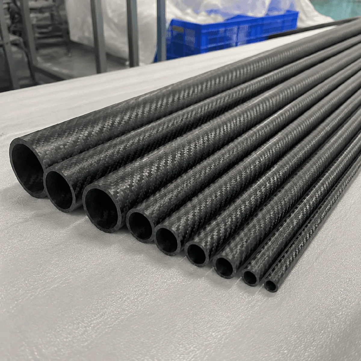
Outside Diameter or Width
Use the outside dimension when the tube locates in a clamp, guide or external fixture. State whether coating and finish are included.
Inside Diameter or Profile
Use the inside feature for sleeves, bonded inserts or telescoping fits. Identify the required engagement length and clearance.
Wall Thickness
Specify wall only where it controls performance or machining. Define measurement locations because local readings may vary around a laminate.
Straightness
State maximum deviation and gauge length. A requirement per meter is not interchangeable with a total deviation over the full component.
Roundness and Concentricity
Choose the characteristic that represents the assembly. Do not demand concentricity when only a local fit surface is functional.
Square and Hex Profiles
Control width, flat-to-flat dimensions, corner geometry and twist according to the faces that locate the component.
Use Machining and Bonded Interfaces Where Precision Is Local
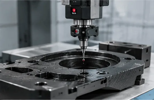
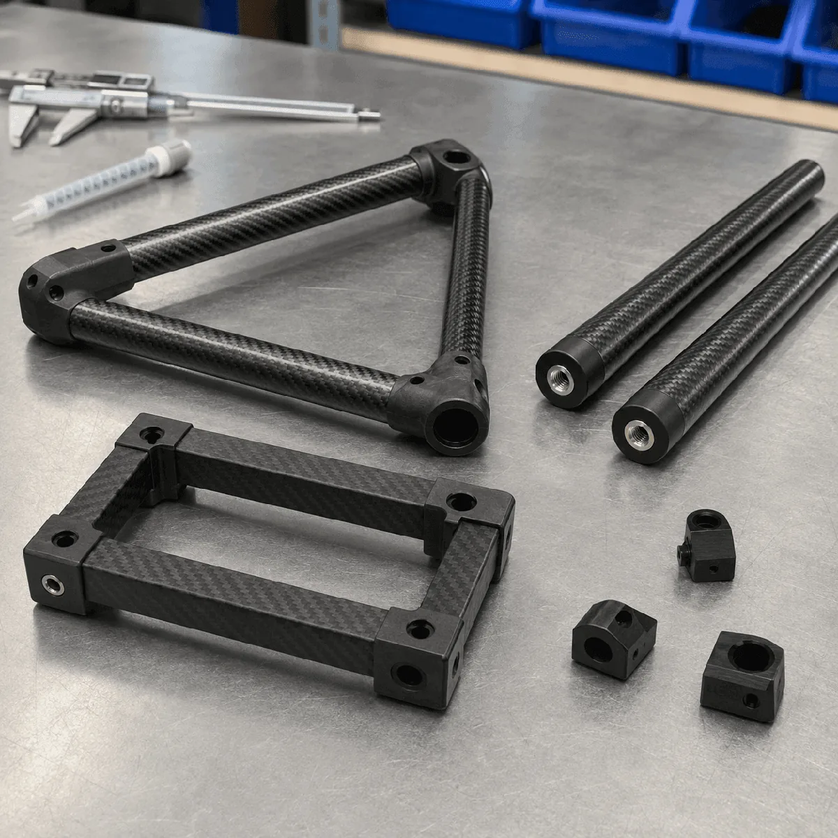
When only a short functional zone needs close control, secondary processing can be more practical than tightening the entire molded tube. Cutting, facing, drilling, milling and bonded sleeves or inserts can create assembly features after the laminate is cured.
Define hole position from stable datums, include minimum edge distances, and show whether dimensions apply before or after bonding. For fitted ends, specify the prepared bond length, adhesive-gap intent, insertion depth and any clocking requirement. Machining cannot correct every laminate or straightness issue, so the complete datum chain still needs review.
Machined End
Control a short OD, ID, face or slot where the mating part requires it.
Bonded Insert
Design the interface around load transfer, surface preparation and adhesive thickness.
Inspection Fixture
Use a functional gauge when several profile features must work together.
Sample Approval
Confirm fit and appearance before releasing repeat production.
How to Specify Carbon Fiber Tube Tolerances Without Over-Tolerancing
First mark the functional datums and critical-to-quality features. Then separate standard manufacturing dimensions from features that require special tooling, selection, machining or inspection. A general title-block tolerance should not silently impose an unrealistic requirement on every as-molded surface.
1 · Identify Datums
Choose references that can be produced and inspected consistently, preferably tied to the actual assembly.
2 · Rank Dimensions
Label critical fits and safety-related characteristics; leave nonfunctional geometry at a practical manufacturing tolerance.
3 · Define the Condition
State as-molded, trimmed, machined, coated or bonded condition and the inspection temperature if relevant.
4 · Add Gauge Lengths
Attach straightness, twist and profile requirements to the length over which they matter.
5 · Agree Measurement
Resolve caliper, micrometer, CMM, fixture, pin gauge or other methods before production.
6 · Review the Stack-Up
Check how tube variation, adhesive gaps, inserts, clamps and mating parts combine in the assembly.
A good RFQ can identify a feature as critical without guessing an arbitrary value. Carbosources can review the drawing and discuss which manufacturing or secondary-operation route is appropriate before confirming the quotation.
Agree on Inspection Before Production
The same dimension can produce different results when measured with different contact points, force, fixtures or datum setups. Composite surfaces may also include texture, resin-rich areas, seams or coatings that must be treated consistently. The inspection plan should therefore identify the characteristic, tool, sampling plan, measurement locations and reporting requirement.
Incoming Reference
Approved drawing revision, material definition and any signed reference sample.
In-Process Checks
Tooling condition, cure/process controls and dimensions appropriate to the manufacturing route.
Final Inspection
Critical dimensions, length, straightness, surface acceptance and machining features.
Documentation
Agree whether a dimensional report, material record, first-article report or custom test is required.
How Tolerance Choices Affect Tooling, Yield and Cost
A tight tolerance can change more than the inspection time. It may require more controlled tooling, a different manufacturing route, additional finishing, slower cutting, dedicated gauges, sorting or a secondary machined interface. It can also reduce production yield when a nonfunctional surface is judged against a requirement tighter than the assembly needs.
The most economical drawing is not the one with the widest tolerances everywhere. It is the one that protects every functional interface while giving the manufacturer enough freedom on noncritical surfaces. During quotation, separate must-have limits from preferred targets. This lets the engineering review compare process capability, tooling investment and repeat-production risk before committing to a value.
Telescoping Tube
Prioritize clearance, profile consistency and straightness across the engagement length. Confirm whether coating and debris clearance are included.
Bonded End Fitting
Control the bonding zone, insertion depth and adhesive gap. A prepared local ID can matter more than the unrestricted internal surface.
Clamped Structural Tube
Define the external contact zone, clamp length and allowable local deformation. Avoid applying the same OD requirement to hidden free spans.
Example: if a 1,500 mm tube only interfaces with a 40 mm-long end fitting, controlling or machining that local zone may be more repeatable than imposing the fitting tolerance over the entire tube. Conversely, a tube used in a long linear guide may genuinely require a full-length straightness and profile requirement. The drawing should make that functional difference visible.
What to Send for a Custom Carbon Fiber Tube Quote
Provide the most complete definition available. Early-stage projects can still be reviewed, but clearly separate confirmed requirements from targets that remain open to engineering discussion.
Geometry
2D drawing and 3D model, profile, OD/ID or width, wall, length and corner details.
Critical Tolerances
Datums, fits, gauge lengths, inspection method and the reason each feature is controlled.
Loads and Environment
Bending, torsion, axial or impact demands plus temperature, moisture, UV and chemicals.
Interfaces
Clamps, bonded inserts, sleeves, holes, slots, bearings, telescoping members and metal contact.
Finish
As-molded, sanded, glossy, matte, painted or another defined surface acceptance level.
Commercial Requirements
Prototype quantity, annual volume, delivery target and required quality documentation.
Carbon Fiber Tube Tolerance FAQ
There is no single tolerance that applies to every carbon fiber tube. Geometry, size, length, laminate, manufacturing process, surface condition and inspection method must be reviewed together.
Selected features can often be controlled through tooling, process planning, machining, bonded interfaces or sorting. Feasibility and cost should be confirmed against the exact drawing.
Specify the dimensions that control function and identify their priority. Tightly constraining OD, ID and wall simultaneously can create an unnecessary or conflicting tolerance loop.
State the maximum permitted deviation, the datum or measurement setup and the gauge length. Also clarify whether the value applies locally or across the full tube.
Machining is useful for local faces, holes, slots and fitting zones that need controlled geometry. The laminate, edge distance, workholding and inspection plan must support the operation.
Send the drawing, CAD model, tube process preference if any, quantity, critical fits, loads, environment, finish and inspection requirements. Achievable values are confirmed after engineering review.
Specify the Features That Matter—Then Confirm the Process
Send your tube drawing, application, expected quantity and critical interfaces. Carbosources can review the profile, laminate direction, manufacturing route, secondary operations and inspection requirements before confirming a quotation.