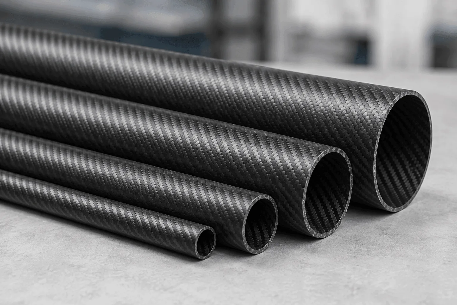
Choose carbon fiber tube wall thickness together with the tube diameter, unsupported span, laminate and connections. Start with the space and interfaces the tube must fit, define the load and permitted movement, then compare candidate sections. A thicker wall is one design option, not a complete specification.
This guide focuses on straight, circular tubes. It separates dimensional arithmetic from structural decisions, using calculated examples rather than a universal thickness chart. The examples are educational comparisons, not Carbosources stock sizes, tested capacities or approved designs.
OD, ID and wall thickness: define the section first
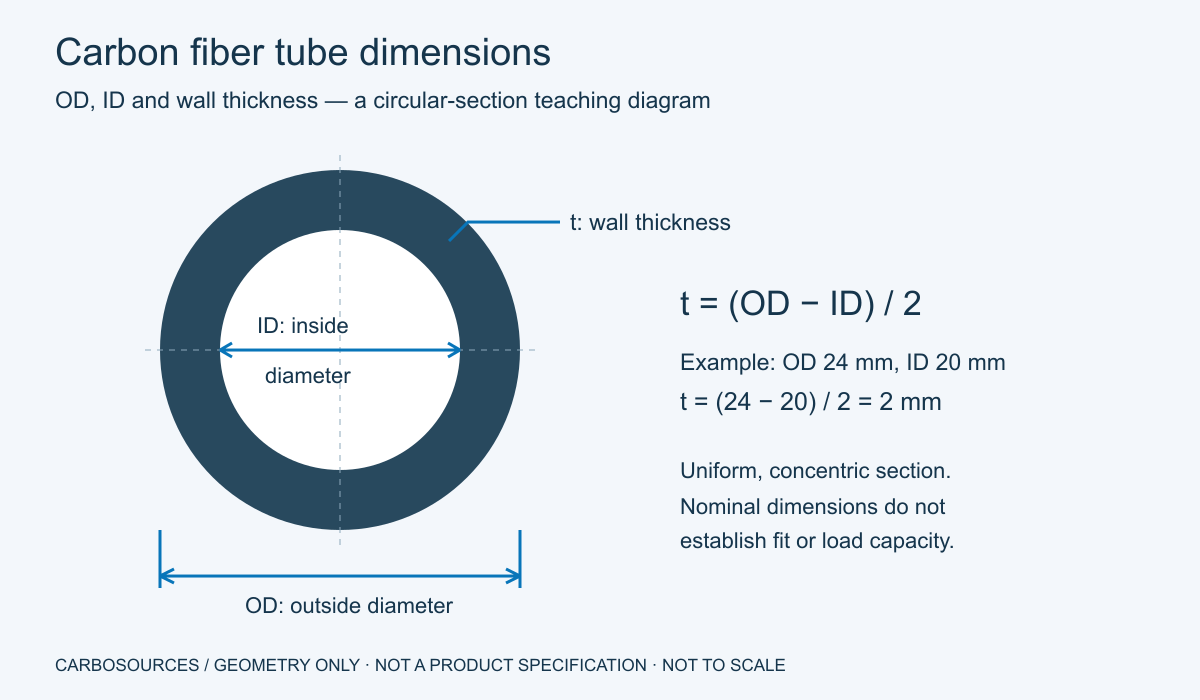
Outside diameter (OD) defines the external envelope. Inside diameter (ID) defines the bore. For an ideal concentric circular tube with uniform wall thickness t:
t = (OD − ID) / 2
Equivalently, ID = OD − 2t and OD = ID + 2t.
A nominal 24 mm OD × 20 mm ID tube has a 2 mm wall. It does not have a 4 mm wall: the diameter difference includes material on both sides. Write the dimension names and units on the drawing rather than relying on an ambiguous “24 × 2” description.
| Fixed requirement | What it means for the other dimensions |
|---|---|
| An existing outside clamp | If OD must stay at 24 mm, increasing the wall from 2 to 3 mm reduces nominal ID from 20 to 18 mm. |
| A required internal passage | If nominal ID must remain 20 mm, increasing the wall from 2 to 3 mm increases OD from 24 to 26 mm. |
| Both OD and ID are fixed | Nominal wall thickness is already determined. Changing it requires revisiting an interface or the overall design. |
Real fit also depends on dimensional variation, surface condition and clearance. A 20 mm nominal insert is not automatically a suitable fit in a 20 mm nominal bore. Keep nominal sizing separate from the acceptance limits explained in our carbon fiber tube tolerance guide.
Before selecting a size, sketch the load and supports
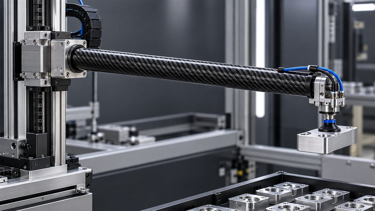
A useful sketch shows more than overall length. Mark the supported regions, free span, load locations and the point where movement matters. A tube held at one end behaves differently from one supported at both ends.
- Load: direction, magnitude and location; distinguish a steady load from repeated motion or impact.
- Span: the distance between effective supports, or the free projection beyond a support.
- Functional limit: permitted deflection, twist or positional error at a defined point.
- Interfaces: clamp diameter, insert envelope, cable passage and space around the tube.
- Operating conditions: temperature, moisture, handling and the expected loading cycles.
For illustration, the elementary small-deflection equation for a slender, uniform cantilever with a transverse end force is δ = FL³/(3EI). It shows why span deserves attention: with the same end force and bending rigidity, doubling the free length increases the calculated bending deflection eightfold. This is a beam-model comparison, not a complete composite-tube design check. Short or shear-flexible members, compliant joints and coupled laminates require more detailed treatment. See Purdue University’s mechanics-of-materials lecture notes for the underlying beam relation.
Larger diameter or thicker wall? Compare the geometry
For a circular annulus, cross-sectional area A = π(OD² − ID²)/4. Its second moment of area about a centroidal bending axis is I = π(OD⁴ − ID⁴)/64. Subtracting the inner circular area from the outer one gives these geometric quantities. A relates to material volume per unit length; I describes the distribution of that material for bending.
The following calculations use ideal, uniform sections. Relative mass assumes equal length and density. Relative bending rigidity additionally assumes the same suitable effective axial modulus, with no change in laminate effects. Actual tubes must be compared using their own construction and engineering data.
| Candidate / OD × ID | Wall | Area A | Second moment I |
|---|---|---|---|
| A / 20 × 16 mm | 2 mm | 113.1 mm² | 4,637 mm⁴ |
| B / 20 × 14 mm | 3 mm | 160.2 mm² | 5,968 mm⁴ |
| C / 24 × 20 mm | 2 mm | 138.2 mm² | 8,432 mm⁴ |
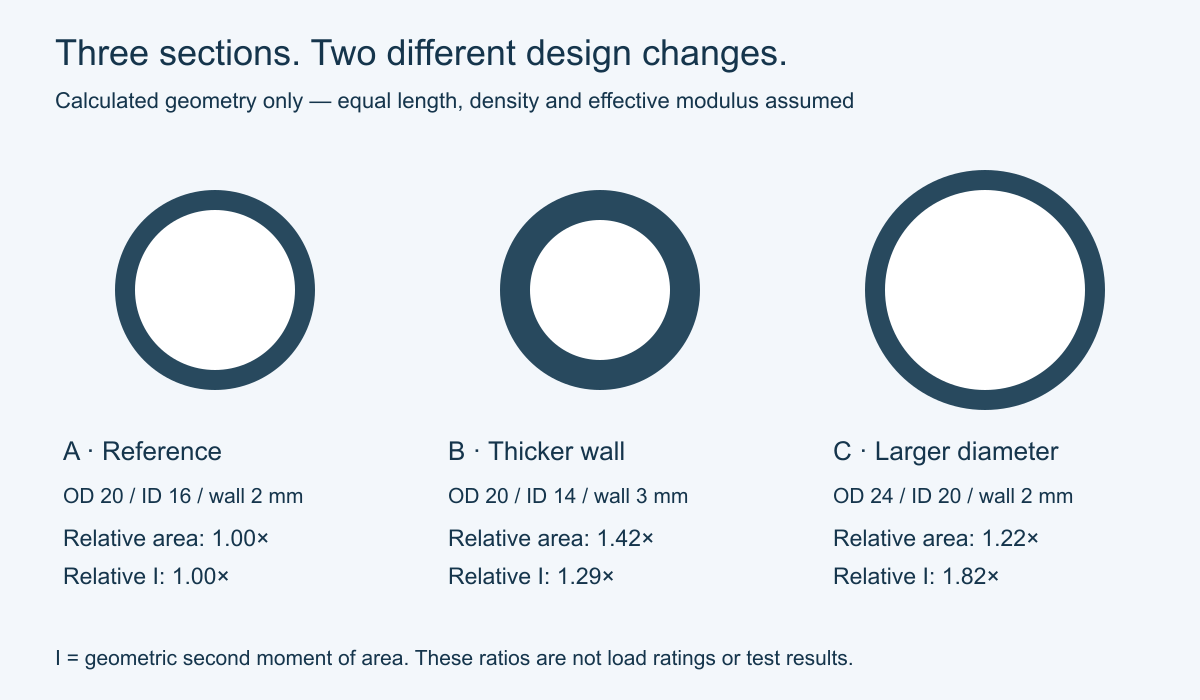
Compared with A, B keeps the 20 mm OD and adds material inward. Its area rises by approximately 42%, while I rises by approximately 29%. C retains a 2 mm wall but increases OD to 24 mm. Its area rises by approximately 22%, while I rises by approximately 82%. These are calculated geometry ratios, not measured product results.
The comparison explains why a larger diameter can be a useful candidate when bending deflection is the main concern and installation space permits it. It does not establish that C is safe, easier to manufacture or better under every load. Local wall stability, torsion, damage, interfaces and laminate design remain separate checks.
The same dimensions can describe different laminates
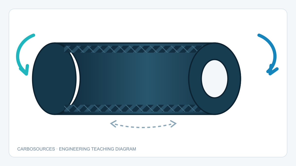
Carbon fiber tube stiffness is directional. In tube terminology, 0° normally follows the tube axis; ±45° reinforcement contributes to shear and torsional response; 90° reinforcement follows the circumference and supports hoop behavior. The amounts and arrangement of these reinforcements influence the result. Rock West Composites explains these orientation effects.
Do not use a raw fiber modulus as the finished tube modulus, or treat a 3K surface weave as a complete structural specification. Ask what laminate or finished-tube data support the stiffness comparison. CKN’s micromechanics explanation describes why composite elastic properties depend on loading direction relative to the fibers.
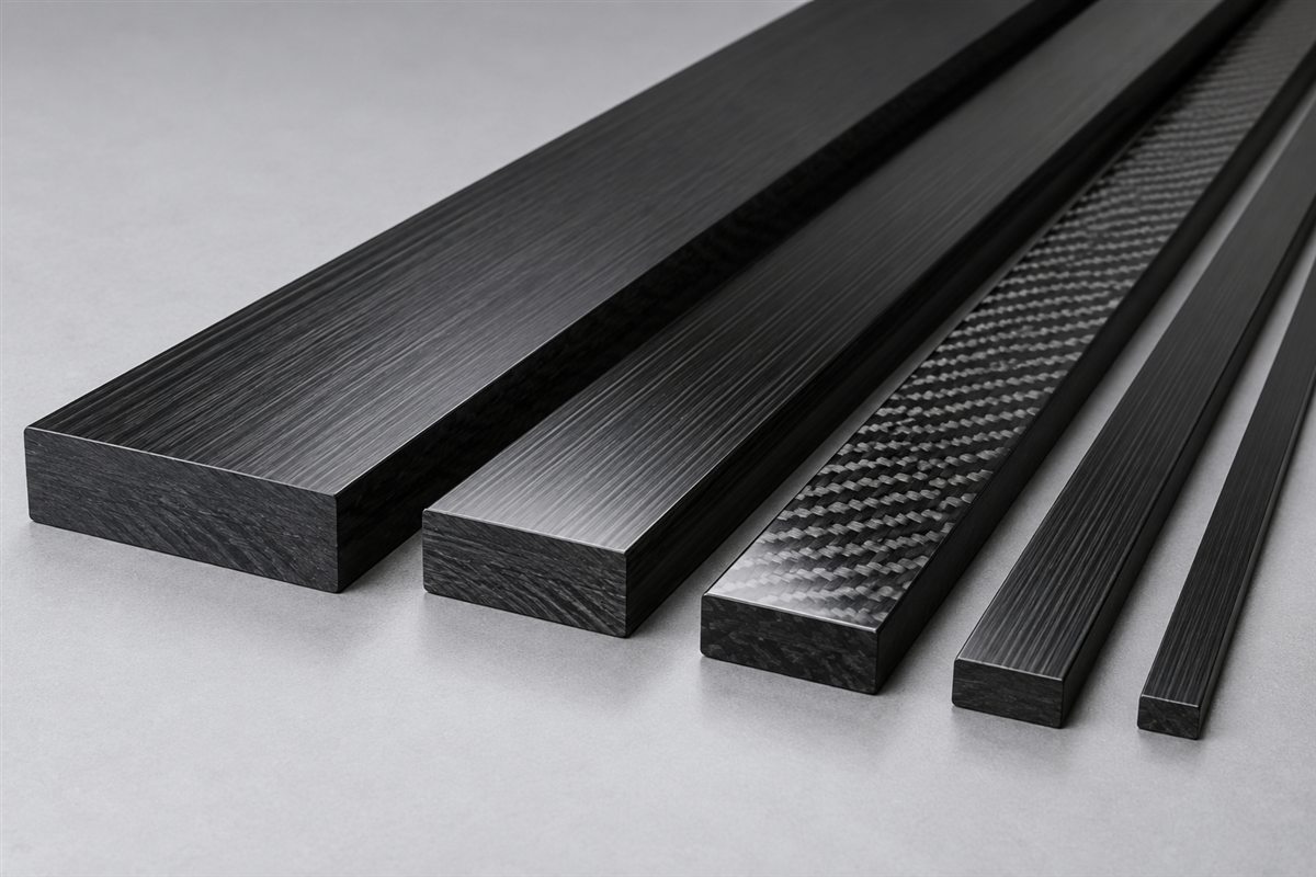
Manufacturing labels alone also leave questions open. For the implications of predominantly longitudinal reinforcement, read our pultruded carbon fiber tube selection notes. Tow count and appearance are discussed separately in 3K carbon fiber, weave and layup explained.
Check the connection before freezing the wall thickness
A tube that meets a global deflection target can still have an unsuitable connection. Review the local load path rather than assuming that extra wall thickness resolves every attachment problem.
| Connection | Questions to resolve |
|---|---|
| External clamp | What is the contact length and shape? How is tightening controlled? Is local support or reinforcement needed? |
| Bonded insert | What controls the bore fit and bondline? How are loads transferred, and how will preparation, cure and acceptance be specified? |
| Through-hole or bolt | Where are the holes relative to the tube end? How will bearing loads and bolt preload be carried without relying on an unsupported wall? |
| Telescoping section | What are the overlap, guide and locking arrangements? How will sliding clearance and play be controlled across actual dimensions? |
Record these details on the assembly drawing. Do not copy a generic bolt torque or adhesive gap into a new composite assembly without checking its materials, geometry and joining method.
Worked example: an OD limit and a required cable passage
Hypothetical geometry screen: an instrument support permits a maximum 24 mm tube OD and requires at least a 16 mm clear bore. The free projection is 400 mm. End loading and the permitted movement have not yet been specified.
B fails the passage requirement: its 14 mm bore is smaller than the required 16 mm. A and C pass the nominal diameter screen. However, A reaches the bore limit with no allowance for variation or routing clearance; C has more nominal bore space and a larger I, but reaches the OD limit.
That is enough to reject B on fit, but not enough to approve A or C structurally. The next steps are to define the load and movement limit, establish actual dimensional allowances, select a suitable laminate, and check the connection. This is the difference between screening a size and validating a component.
Turn the selected size into a usable specification
- Name OD, ID, wall thickness and finished length, with units and a drawing revision.
- Identify which dimensions are functional controls and which are reference or derived dimensions; avoid independently over-constraining all three diameter/wall values.
- Mark support locations, free span, load points and allowed movement.
- Specify the required material construction or the performance evidence needed to approve it.
- Show holes, inserts, clamping zones, end details and the required clear passage.
- Agree dimensional inspection, functional checks and any structural validation before approval.
For square, rectangular or hexagonal sections, replace OD/ID with the appropriate outside and inside dimensions and include corner radii. The circular-annulus calculation above does not apply unchanged. The Carbosources carbon fiber tube overview provides context for the different section types.
Carbon fiber tube wall thickness: common questions
Is a 1 mm or 2 mm wall thick enough?
Thickness alone cannot answer that. The diameter, span, load, laminate and connection all need to be defined. A thickness label is not a load rating.
Does increasing wall thickness always make a tube stiffer?
At fixed OD and unchanged effective material properties, adding wall inward increases the geometric second moment of area. It also adds material and reduces the bore. Whether it is the useful design change depends on the constraints.
How do I calculate wall thickness from OD and ID?
For a concentric, uniform circular section, subtract ID from OD and divide by two. Actual minimum wall and local variation require appropriate inspection rather than only nominal arithmetic.
Can two tubes with the same OD and wall have different performance?
Yes. Matching dimensions do not establish matching fiber architecture, laminate properties, manufacturing quality or joint behavior. Compare the relevant finished-tube data.
Should I choose the bore or the outside diameter first?
Start with the interface that is constrained. An existing clamp constrains the outside; an insert or internal passage constrains the bore. If both are fixed, they jointly determine nominal wall thickness.