
Carbosources supports carbon fiber prototyping and tooling development for custom OEM parts. We review your CAD drawings, manufacturing route and sample acceptance requirements to plan custom carbon fiber prototypes around fit, function and production needs.
Tooling scope, materials, interfaces and the purpose of the sample are considered together before the first part is made.
Drawing Review · Tooling Planning · Prototype Manufacturing · Sample Evaluation
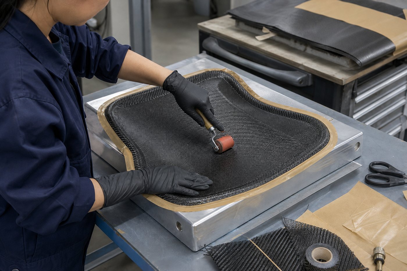
The starting point depends on the part geometry and what the sample needs to validate. Use the routes below to identify the drawing and interface information needed for review.
Review a flat component around its outline, thickness, hole pattern and mounting datums. Include the laminate requirement, critical tolerances and mating-part drawing. Suitable sheet material and machining fixtures are reviewed before deciding whether dedicated forming tooling is needed.
Provide the tube section, length, wall construction and mating clamp or insert. For an assembly sample, identify the installed length, fitting orientation and the interfaces that control fit. Tooling and joint requirements are reviewed together.
Provide the CAD model, visible faces, trimmed edges and assembly interfaces. The review considers forming geometry, release, laminate intent and any secondary machining or locating fixtures. The sample acceptance plan should state what the prototype must demonstrate.
A useful prototype has a defined question to answer. Carbon fiber prototypes for fit and assembly may need a different build and acceptance plan from a sample intended for load testing. State the decision you need to make before selecting the material, process or tooling.
Check the installation envelope, hole pattern, mating dimensions, clearances and assembly sequence. Include the surrounding components or an assembly drawing so a correct outline is not mistaken for a complete fit check.
Define the stiffness, loads or environmental conditions to be evaluated. A functional prototype requires a relevant laminate, resin, interfaces and agreed test method; a cosmetic sample cannot establish these results.
Review forming, release, trimming, machining and assembly. Identify which features can be repeated in production and which operations or tools may need further development.
A fit-check sample does not automatically validate structural performance. Any differences between the prototype and planned production construction should be documented.
Tooling for carbon fiber parts can include forming molds, mandrels, dies, locating fixtures and trimming tools. Not every custom part requires a new mold. The appropriate route depends on geometry, the required construction and available tooling.
| Part type | Tooling to review | Inputs that affect the decision |
|---|---|---|
| CNC-machined plate parts | Suitable sheet material and any locating, drilling or machining fixtures. A dedicated forming mold may not be necessary. | Outline, thickness, hole pattern, datums, laminate requirements and quantity. |
| Tubes and constant profiles | Compatibility with existing tooling or the need for a new mandrel, die or profile tool, depending on the manufacturing route. | Inside and outside dimensions, wall thickness, length, load direction and end connections. |
| Curved molded components | Forming tools plus any trimming, drilling or assembly fixtures. | 3D geometry, visible faces, parting and release constraints, interfaces and anticipated volume. |
Existing tooling must be checked against the complete requirement. A similar outside shape does not establish the correct wall, inside dimensions, laminate or surface condition.
For CNC-machined carbon fiber prototypes, show the reference edges and critical hole locations. For tube projects, include the mating insert or clamp.
Carbon fiber mold development starts with the part requirements and selected forming process. Prototype tooling for composites should suit what the sample must demonstrate while making later production requirements visible.

Review parting lines, draft where needed, internal radii and tool access. Undercuts or trapped features may require a different tool arrangement or a change to the part design.
Tool material and construction need to suit the agreed forming and curing conditions. Thermal movement, sealing, support and handling should be considered for the actual process.
Identify which face is cosmetic, where trimming occurs and how holes or inserts are located. The tool surface and later machining operations contribute different features to the finished part.
The tooling choice for a small evaluation batch may differ from a tool intended for repeat production. Discuss expected volume, maintenance and likely design changes before committing to the approach.
For custom molded carbon fiber prototypes, separate the cost of the part from the scope of mold development and any secondary fixtures. The final choice is confirmed through project review.
Carbon fiber prototype manufacturing works best when each stage ends with a clear decision. The sequence below is a project planning framework; work scope, testing and approval responsibilities are agreed for the specific component.
Send the CAD model, dimensioned drawing, application and sample quantity. Mark the features that control fit and state what the prototype must prove.
Confirm: Drawing revision, interfaces and acceptance objectives.
Review laminate intent, manufacturing route and tool requirements. Clarify any assumptions affecting the sample or later production.
Confirm: Proposed build route, tooling scope and open questions.
Prepare the agreed molds or fixtures, with attention to geometry, release and the surfaces used to locate the part.
Confirm: Tool readiness and checks relevant to the first build.
Produce the sample through the agreed forming or machining route, including specified trimming, holes, fittings and assembly operations.
Confirm: A sample identified against the agreed build requirements.
Check the relevant dimensions and assembly features. Perform separately agreed testing where required and record customer feedback.
Confirm: Measured or observed results and an actionable issue list.
Review changes, define any repeat work and confirm the approved part version before preparing the next stage.
Confirm: Approval basis, revision record and remaining production actions.
Carbon fiber prototyping from CAD drawings also requires information a model may not contain: tolerances, datum references, load directions, visible surfaces and mating details. See what to include in a drawing review →
Turn each critical requirement into a check that can be recorded against the drawing revision. Agree the measurement or test method, who performs it and what constitutes acceptance before the sample is made.
| Check | Define the requirement and its evidence |
|---|---|
| Fit | Define: Mating parts, datum faces, hole locations and required clearances. Evidence: An agreed dimensional record or documented assembly check. |
| Surface | Define: Visible faces, edge condition and an agreed appearance reference. Evidence: Inspection against the stated reference and viewing conditions. |
| Function | Define: Loads, supports, environment, measurement points and pass criteria. Evidence: Separately agreed analysis or testing; appearance alone cannot establish performance. |
| Interfaces | Define: Inserts, fasteners, fitting orientation and installed dimensions. Evidence: Interface measurements and the agreed assembly or joint checks. |
| Release | Define: Drawing revision, sample identity, deviations and approval responsibility. Evidence: An approval record identifying what is accepted and what remains open. |
A hypothetical plate must locate on an existing bracket. Name the mounting face and locating holes, then identify the clearances and drawing revision. Record the hole-location checks and whether the plate assembles as intended. If only fit was checked, the approval should say so: stiffness, fatigue and environmental suitability remain separate requirements. This example is not a customer project or a reported Carbosources test.
A change should identify the problem, affected feature and required outcome. Carbon fiber prototype design changes may affect the tool, laminate, machining program, interfaces or validation scope. These effects should be reviewed before revised work begins.
Identify the dimensional or manufacturing difference, review its cause and agree on the corrective action and recheck. Keep the original acceptance requirement visible.
Record the new revision and evaluate whether existing tooling can be modified. Confirm effects on cost, schedule and any repeat sample work before proceeding.
Revisit the load, stiffness or interface requirement. A different laminate or joint may require a new verification plan even when the outside shape remains unchanged.
Tooling payment and tooling ownership should not be treated as interchangeable assumptions. Record the agreed terms for the project; no universal revision allowance or tool-life commitment is implied.
The transition from carbon fiber prototype to production requires a defined baseline. Approval of one sample does not by itself establish a complete production specification.
If the prototype used different tooling or a different process from the intended production route, review which results transfer and which must be checked again.
Prepare the design inputs with the Carbon Fiber Prototype Design Checklist before defining the sample build and acceptance plan.
Not always. A flat component may be machined from suitable sheet material, while a shaped part may need a forming tool. Tubes and profiles require a check of existing tooling against the requested section and construction. Secondary machining or assembly fixtures may still be needed.
Provide a CAD model where available and a dimensioned drawing identifying revision, datums, critical tolerances and material requirements. Add the application, quantity, mating components and what you want the sample to validate. Confirm the file format during project review.
A physical sample can help communicate shape and finish. It does not necessarily reveal the internal laminate, resin, original loads or acceptance requirements. Confirm measurement, reverse-engineering scope and permission to reproduce the design before work begins.
Geometry, material and laminate requirements, new tooling, machining, inserts, sample quantity and testing all affect scope. Frequent design changes or additional sample rounds can add work. A useful quotation separates tooling, sample manufacture and any agreed inspection or testing.
Ownership, storage location, maintenance and future use should be stated in the project agreement. Include arrangements for modification, transfer or end of use where relevant. Do not infer ownership from a tooling line item alone.
Changes can be reviewed, but feasibility depends on the feature and manufacturing route. Some updates may use the existing tool; others may require tool modification or a new build. Agree on the revised drawing, cost, timing and validation before proceeding.
Confirm the drawing revision, materials and construction, critical interfaces, acceptance criteria and any outstanding test requirements. Record the sample approval and identify differences between prototype and production methods.
Send your drawing or CAD model, application, prototype quantity and the features you need to validate. Include mating parts, critical dimensions and any testing requirements so the development scope can be reviewed.