
Home › Carbon Fiber Tubes › Carbon Fiber Tube Assemblies
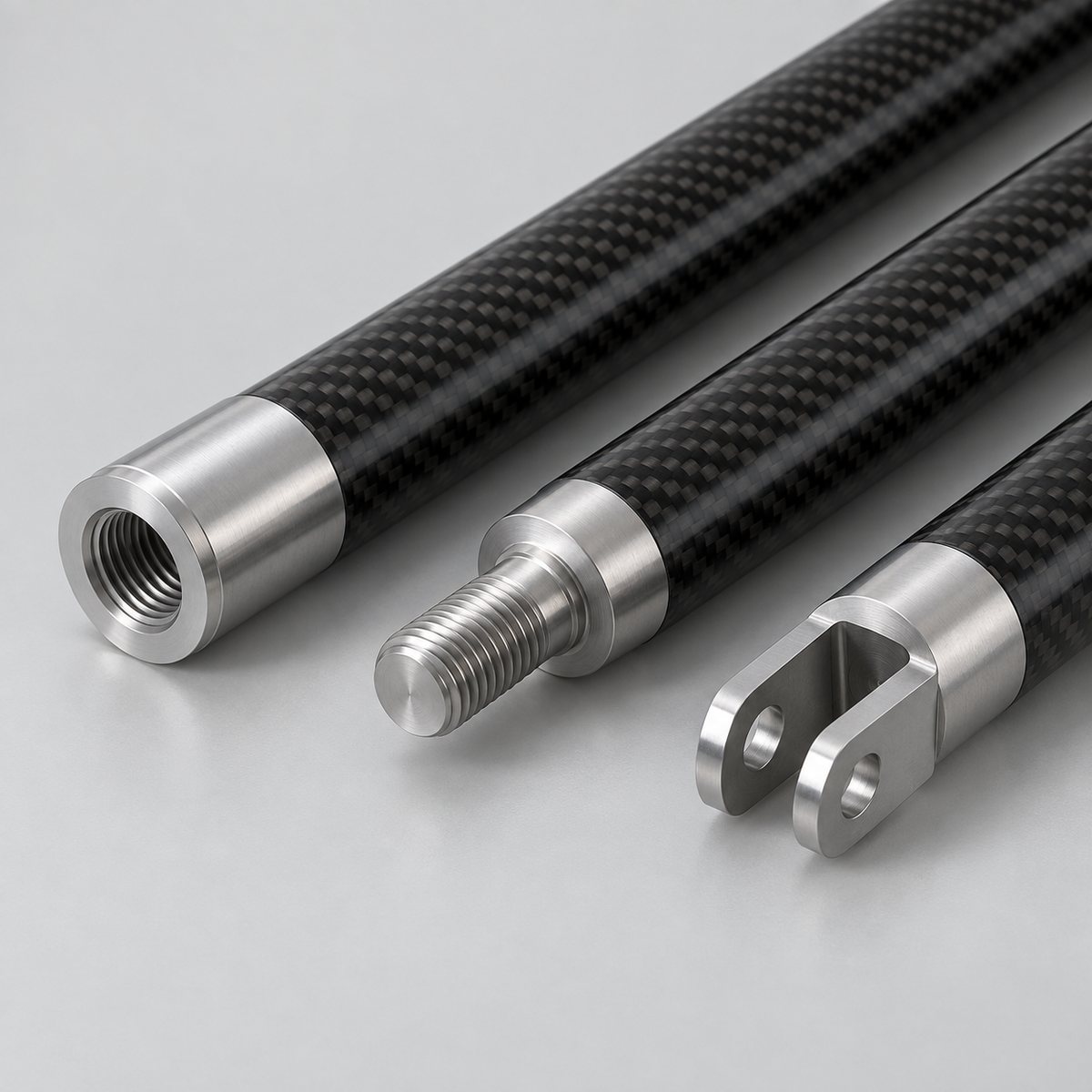


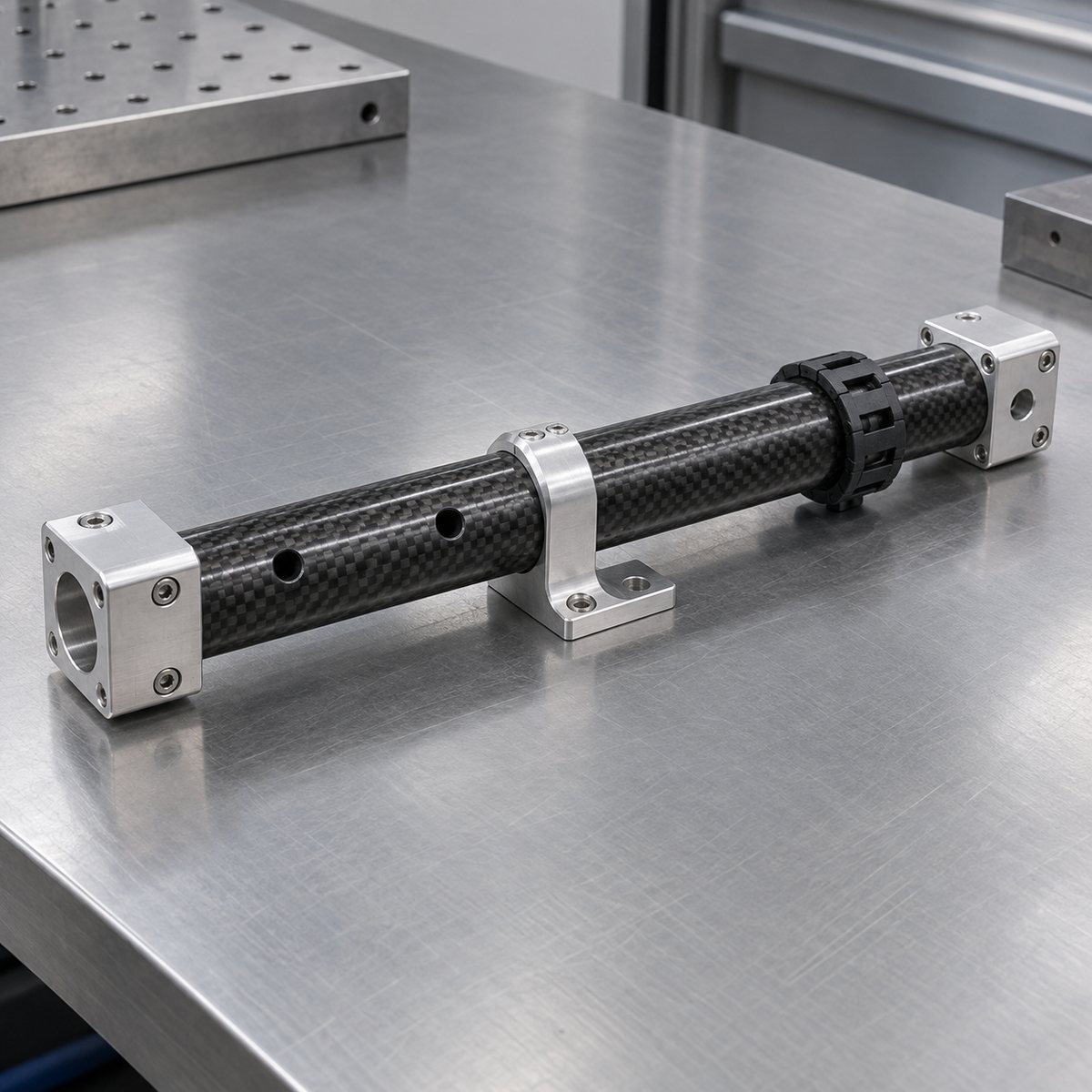
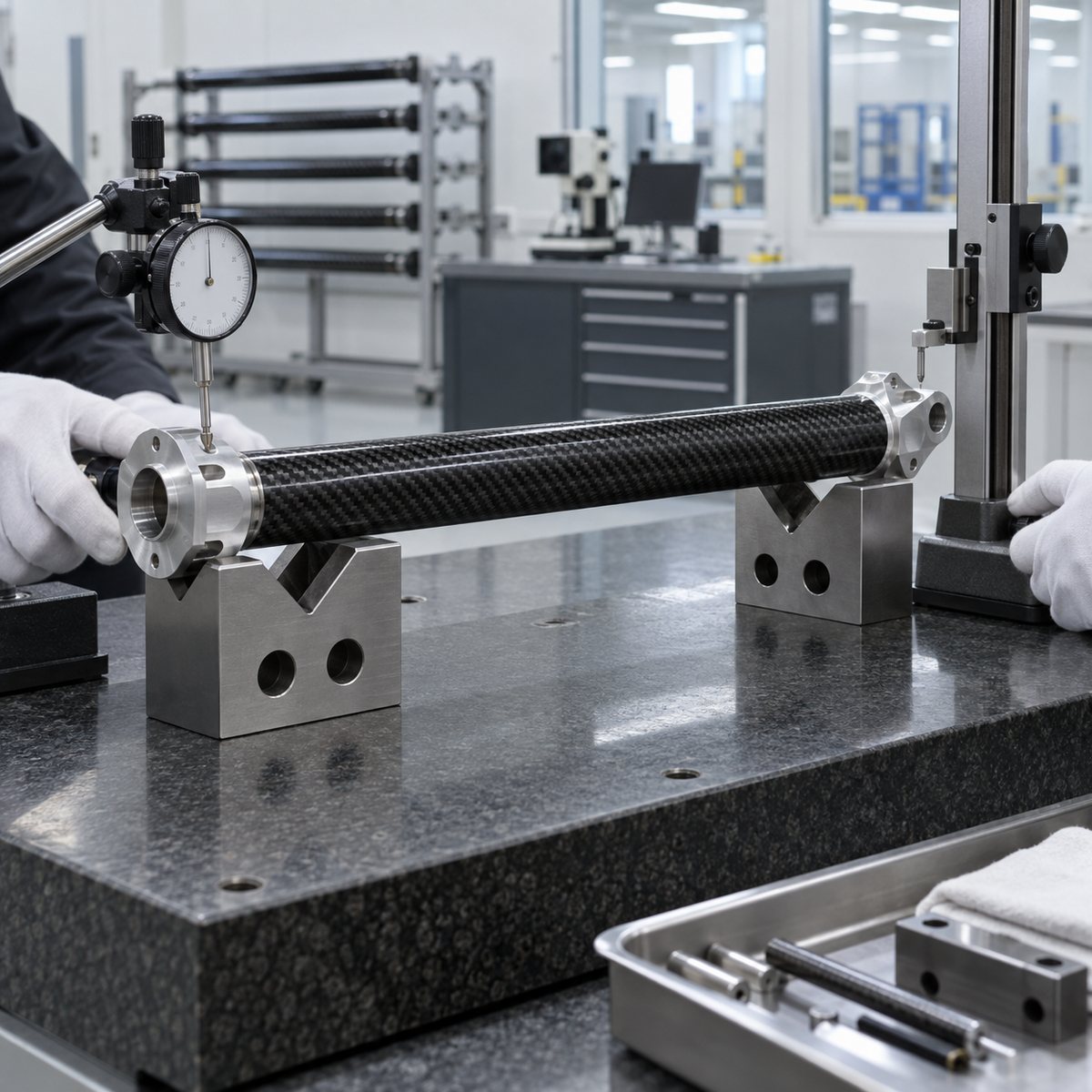
CUSTOM TUBES WITH READY-TO-INSTALL INTERFACES
Custom Carbon Fiber Tube Assemblies
Carbosources supplies custom carbon fiber tube assemblies for OEM projects that need more than a cut tube. The assembly can combine a drawing-controlled carbon tube with bonded inserts, sleeves, end fittings, brackets, drilled features or removable connectors. Tube geometry and joint design are reviewed together because the interface often controls how load enters the laminate.
Send the complete assembly drawing, not only the tube dimensions. State the load direction, attachment method, overall length, interface orientation, quantity and service environment so the carbon fiber tube assembly can be quoted as one controlled component.
| Assembly input | What the RFQ or drawing should define |
|---|---|
| Tube geometry | Outside diameter, inside diameter, wall thickness, length and section shape |
| Tube construction | Required manufacturing method, layup intent or load and stiffness requirement |
| End interfaces | Insert, threaded fitting, clevis, sleeve, bracket, clamp or customer-supplied hardware |
| Joint function | Permanent, removable, adjustable or field-serviceable connection |
| Loads | Tension, compression, bending, torsion, impact, vibration and load introduction points |
| Machining | Cut length, holes, slots, datum faces and orientation features |
| Assembly control | Overall length, concentricity, runout, angle and clocking between interfaces |
| Acceptance | Critical dimensions, cosmetic limits, bond inspection and agreed testing |
A useful quotation distinguishes the tube requirement from the finished interface requirement. If the fitting already exists, provide its drawing and material. If it must be developed, provide the mating component and installation envelope. Carbosources confirms feasible tube, fitting and bonding options after reviewing the application; no universal joint geometry fits every assembly.
Define the Complete Assembly, Not Only the Tube
A completed assembly should be defined from one end interface to the other. Tube length alone does not establish the finished length after inserts, shoulders, caps or clevises are installed. Use named datums and show where each length starts and stops. If two fittings must share the same angular orientation, dimension the clocking relationship rather than relying on a product photograph.
Outside diameter is only one fit condition. An internal insert also depends on inside diameter, wall thickness, roundness and available insertion depth. An external sleeve changes the maximum envelope and can interfere with nearby hardware. Review the tube diameter and wall-thickness guide when preparing the initial geometry.
Choose the tube construction from the assembly loads. A primarily axial member, a torque tube and a beam with an offset end load do not need the same reinforcement. Local drilling, clamping and bonded inserts can also change the required end construction. The drawing should identify where the tube carries bending, torque or concentrated loads so the laminate and interface can be reviewed together.
Select the Joint and End Fittings
A bonded carbon fiber tube assembly may use a machined insert or end fitting bonded into the tube bore. The joint review should cover insert material, insertion length, bond area, fit, adhesive gap, shoulder location and how the applied load reaches the tube wall. Threads are normally provided by a bonded or molded fitting rather than cut directly into a thin composite wall.
Tube-to-tube connections may use an internal sleeve, external ferrule or another approved connector. An internal sleeve keeps a clean outer profile but is limited by the tube bore. An external ferrule can provide a different bond envelope but increases the outside diameter. A sectional assembly may permanently bond one side and use a controlled slip fit or mechanical retention on the removable side.
Carbon fiber tube end fittings should be specified by interface function, material, geometry, retention method and the load they must transfer into the tube.
| Joint approach | Useful when | Items to review |
|---|---|---|
| Bonded insert | A compact permanent end interface is needed | Insertion length, bond gap, fitting material and load path |
| Internal sleeve | Two tube sections need a smooth outside profile | Bore tolerance, alignment, overlap and retention |
| External ferrule | Additional external diameter is acceptable | Envelope, bond area, edge transitions and handling |
| Threaded fitting | The assembly must connect to standard hardware | Thread form, locking method, torque and fitting support |
| Clamp or quick release | Adjustment or repeated service is required | Contact pressure, slip, wear and tube-wall protection |
Connector names do not establish performance. Permanent and removable joints should be evaluated against the actual load direction, duty cycle, environment and maintenance plan.
Transfer Loads without Local Tube Damage
The highest stress in many carbon fiber tube assemblies occurs close to an interface. A short rigid fitting can introduce load abruptly, while a cross-hole can interrupt fibers and create a local stress concentration. Clamps can damage a thin wall if pressure is concentrated over a small area. These effects must be considered before the tube and hardware drawings are released.
Local solutions may include a longer load-transfer region, additional end reinforcement, a sleeve, a shaped adhesive fillet, a larger clamp contact area or a fitting that supports the tube wall. The appropriate choice depends on the assembly, and any load claim should be based on an agreed design and test method rather than copied from a different tube.
Connecting carbon fiber to aluminum, stainless steel, titanium or another material also introduces environmental questions. Review thermal expansion, moisture, surface finish and possible galvanic interaction where relevant. Hardware material should be chosen from the full operating environment, mass target and maintenance requirement, not appearance alone.
For related fit and acceptance questions, use the carbon fiber tube tolerance guide. It explains why tube dimensions and finished-assembly tolerances should be specified separately.
What to Put on the Assembly Drawing
- Finished geometry: total length, tube dimensions, interface dimensions and assembly envelope.
- Datums: reference axis, end face, clocking feature and orientation between both ends.
- Hardware: fitting drawings, materials, threads, supplied components and mating parts.
- Joint: permanent or removable function, bond region, sleeve, clamp or locking feature.
- Machining: hole and slot positions, cutouts, countersinks and deburring requirements.
- Loads: magnitude, direction, load introduction, duty cycle, impact and vibration.
- Environment: temperature, moisture, chemicals, outdoor exposure and maintenance.
- Inspection: critical dimensions, alignment, runout, bond appearance and requested tests.
Provide DXF for two-dimensional hole or slot patterns and STEP or IGES for fittings and complete interfaces. A dimensioned PDF should identify critical tolerances and drawing revision. If the assembly mates to a customer component, include that geometry or a controlled interface drawing.
CNC cutting, end squaring, drilling and orientation features can be reviewed when the tube construction supports them. The carbon fiber CNC machining service lists the drawing information used for secondary processing. State whether Carbosources supplies the fittings, receives customer-supplied hardware or assembles components from multiple sources.
Assembly Control and Inspection
Assembly control begins before adhesive is applied. Fittings, tube bores and bond regions should be checked for fit, cleanliness and damage. Fixtures may be needed to control finished length, concentricity, runout, angular orientation or bracket position during curing. The drawing should make clear which relationships are functional.
Final inspection may cover total length, insert depth, end-face position, fitting clocking, hole location, concentricity, runout, bond-line appearance, excess adhesive removal and damage around machined features. If a proof load, pull-out test, torque check or destructive qualification sample is required, define the method, direction, sample plan and acceptance value before production.
Typical applications include robotics and automation arms, camera and inspection booms, UAV supports, antenna structures, measuring equipment, lightweight machine members and portable industrial tools. Each application still needs its own load and interface data. Packaging should also protect protruding fittings and prevent long assemblies from bending or carrying stacking loads during transport.
Send Your Carbon Fiber Tube Assembly Drawing
Send the tube dimensions, complete assembly drawing, fitting details, quantity, loads, service environment and critical inspection points. Carbosources will review the tube, connector, bonding, machining and fixture requirements before quotation.
Frequently Asked Questions
Can metal fittings be bonded into carbon fiber tubes?
Yes, when tube geometry, fitting material, bond area, adhesive process and load path are reviewed as one joint.
How can two carbon fiber tubes be connected?
Possible approaches include internal sleeves, external ferrules, bonded inserts, threaded fittings, clamps and quick-release joints. The required load, envelope and service method determine the choice.
Can the assembly be removed or adjusted?
A removable design can use threaded, clamped, pinned or slip-fit interfaces. State how often it will be assembled and whether field tools are available.
Can holes be drilled after bonding?
The machining sequence should be planned from the datum and joint design. Drilling through a tube or fitting can affect fibers, alignment and bond integrity.
What information is needed for a quote?
Provide tube dimensions, finished length, fittings, joint function, mating geometry, loads, quantity, environment, tolerances and requested inspection or testing.