A carbon fiber prototype is useful only when everyone agrees on the question it must answer. One sample may exist to check envelope and hole locations. Another may need production-intent material, tooling and cure control so that structural or dimensional results are meaningful. Treating both samples as equivalent creates false confidence.
Composite parts add variables that a 3D shape alone cannot control. Fiber direction, ply sequence, resin system, tooling surface, cure route, machining datum and bonded interfaces can all affect the finished component. A CAD model may describe the nominal geometry while leaving these manufacturing and acceptance decisions unresolved.
This carbon fiber prototype design checklist organizes those decisions from the first controlled model through design for manufacturability, tooling, secondary operations, inspection and first-article approval. It is intended as a project-planning guide. Component allowables, test loads and acceptance limits still need to come from the applicable design authority and project requirements.
1. Define What the Prototype Must Prove
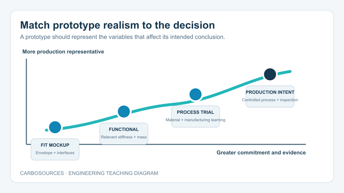
Start with a decision, not a manufacturing method. A clear prototype statement can usually be written as: “This article will be used to determine whether…” followed by one or two measurable questions.
Common prototype purposes include:
- Fit and interface: Does the part occupy the correct envelope, clear adjacent hardware and align with its mating features?
- Appearance: Does the visible surface, weave presentation, gloss, color or edge finish meet the agreed reference?
- Functional behavior: Does the component provide the required stiffness, weight, motion, sealing or handling behavior?
- Structural evidence: Does a defined material and laminate respond acceptably under a controlled test condition?
- Manufacturing learning: Can the selected reinforcement be formed, consolidated, released, trimmed and inspected using the intended route?
- Production readiness: Can the controlled process repeat the approved part, documentation and inspection results?
Do not require every early prototype to represent every production feature. That usually adds cost without improving the decision. Instead, document which characteristics must be representative and which may be simplified.
| Prototype level | Primary question | Must be representative | May be simplified |
|---|---|---|---|
| Geometry mockup | Will it fit and assemble? | Envelope, interfaces, access and key datums | Laminate, resin, finish and production process |
| Appearance sample | Is the visible result acceptable? | Tool-side texture, weave presentation, coating and edge standard | Structural layup and some hidden geometry |
| Functional prototype | Does the design perform its task? | Relevant geometry, interfaces, stiffness and mass distribution | Production cycle time and some cosmetic details |
| Production-intent article | Can the design and process be released? | Controlled material, layup, tooling, cure, machining and inspection | Only explicitly approved noncritical details |
This separation prevents a printed fit model from being treated as proof of laminate performance, or a hand-made structural sample from being treated as proof of production repeatability.
2. Establish the Controlled Design Inputs
The team needs one unambiguous design baseline. A collection of files is not a baseline if different files contain conflicting dimensions or revisions.
Control the 3D model
The three-dimensional model normally defines the nominal shape. Record the file format, native software when relevant, revision, units and date. Neutral files such as STEP or Parasolid can support exchange, but the receiving system should still be checked for missing surfaces, changed units or geometry translation errors.
Identify whether the model represents the molded shape, the trimmed part, the machined final part or an assembly. These states may not be identical. A molded shell can include trim allowance; a cured plate may be machined to its final perimeter; an insert pocket may be created after cure.
Use the 2D drawing to control acceptance
The drawing should identify dimensions and requirements that determine acceptance. Useful drawing content includes:
- part number, title, revision and units;
- datums and the coordinate system used for measurement;
- critical-to-function dimensions and tolerances;
- hole sizes, positions, countersinks and thread or insert details;
- finished thickness and where it is measured;
- trim lines, edge radii and corner conditions;
- controlled surfaces and cosmetic zones;
- material or laminate references;
- notes for bonding, sealing, coating or marking;
- inspection and reporting requirements.
Avoid controlling the same feature differently in the CAD model, drawing and separate spreadsheet. If a supplemental specification is needed, give it an identifier and revision and reference it from the drawing.
Add the assembly context
A standalone part model may hide the real constraint. Include mating geometry or an interface control drawing when assembly clearance, bolt access, adhesive gap, alignment or motion matters. Mark which adjacent components are fixed and which still may change.
3. Record Loads, Environment and Consequence of Failure
A carbon fiber part cannot be designed from external dimensions alone. Fiber-reinforced laminates are directional, and the load path influences the material architecture, local reinforcement and attachment strategy.
The prototype brief should describe:
- load direction and point of application;
- tension, compression, bending, torsion, bearing, peel or combined loading;
- normal operating load, occasional peak and relevant cycle count;
- impact or handling events that should be considered;
- temperature, humidity, water, UV and chemical exposure;
- contact with conductive metals and the need for electrical isolation;
- dimensional stability requirements;
- the consequence of excessive deflection or failure.
Separate known values from estimates. A requirement such as “must feel rigid” cannot be verified consistently. A displacement limit at a stated load and support condition creates a testable target. Where reliable load information is unavailable, the prototype plan should say which uncertainty is being investigated rather than disguising it as a fixed requirement.
4. Define Material and Laminate Intent
“Carbon fiber” does not identify a complete material system. Likewise, a surface description such as “3K twill” does not define the internal reinforcement or structural behavior.
For a production-intent prototype, define or deliberately leave open the following items:
- reinforcement form: woven fabric, unidirectional tape, braid, tow or chopped format;
- fiber grade or required performance class;
- resin system and relevant service-temperature requirement;
- ply orientations and stacking intent;
- symmetry, balance and local reinforcement;
- nominal cured-ply count or finished thickness;
- core material and density for sandwich construction;
- cosmetic surface ply and visible weave direction;
- permitted substitutions and who may approve them.
The article on plain, twill and unidirectional carbon fiber explains why surface weave and internal load-carrying architecture are different decisions. The carbon fiber sheet thickness guide also shows why thickness should be evaluated together with span, support and load rather than selected as an isolated number.
If the purpose of an early prototype is geometry only, production material may remain open. Label that limitation clearly so later users do not test the surrogate as though it represented the final laminate.
5. Run a Composite DFM Review
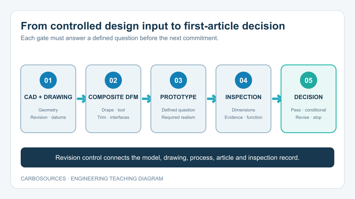
A composite DFM checklist asks whether the intended material can follow the geometry, consolidate, cure, release, trim and accept its secondary operations. It should occur before tooling is released.
Review curvature, corners and drape
Sharp internal corners can make reinforcement bridge across the tool instead of following it. This can create resin-rich regions, wrinkles or incomplete consolidation. The practical radius depends on material form, ply orientation, thickness, tool access and process, so a universal minimum should not be applied without review.
Double curvature, deep channels and rapid section changes deserve special attention. A woven fabric may shear to follow a contour, while unidirectional material has different handling limits. The review should identify where darts, splices, tailored blanks or a different preform concept may be required.
Review draft, undercuts and demolding
Define the tool side, pull direction and parting strategy. Zero-draft walls, reverse features and trapped flanges may require split tools, removable inserts, collapsible mandrels or a geometry change. Consider the cured part’s stiffness: a shape that can be demolded in a flexible polymer may not release safely as a rigid laminate.
Review thickness transitions
Abrupt ply terminations and rapid changes in laminate thickness can create local waviness and interlaminar stress. Identify taper regions, reinforcement patches and transition lengths in the design definition. A smooth exterior surface does not prove that the internal transition is controlled.
Review holes, inserts and free edges
Check hole edge distance, fastener access, washer or flange contact area, insert geometry and local load introduction. Holes that are acceptable in a metal version may be poorly placed for a laminate. The DFM review should also decide whether holes are molded, drilled, routed or located from an assembly fixture.
Review measurement access
A requirement is incomplete if it cannot be inspected. Confirm that datums are physically accessible after demolding and trimming, and that the selected gauge, CMM probe, scanner or fixture can reach each controlled characteristic.
6. Select the Prototype Route and Tooling Level
The best prototype route is the one that represents the variables required for the decision. It is not automatically the fastest method or the final production process.
| Route | Useful for | Main limitation |
|---|---|---|
| Non-composite mockup | Envelope, handling, access and assembly sequence | Does not represent laminate behavior or production processing |
| CNC-machined cured plate | Flat brackets, interfaces and rapid geometry changes | Limited to plate-based geometry and an existing laminate |
| Soft or temporary tooling | Shape, appearance and early molding learning | May not represent long-run dimensional stability or tool life |
| Production-intent tooling | Process, repeatability and final surface validation | Higher commitment before all design risks are closed |
| Representative subcomponent | Local joint, corner, insert or process validation | Does not prove the behavior of the complete assembly |
The broader guide to choosing a manufacturing process for custom carbon fiber parts compares how geometry, quantity and quality requirements influence the manufacturing route.
Tooling decisions should account for cure temperature, vacuum or molding pressure, dimensional stability, expected pulls, repairability, surface requirement and inspection. Record whether the prototype tool is disposable, bridge tooling or intended to continue into production.
Related reading: Carbon Fiber Prototyping & Tooling Development explains how sample objectives, tooling scope and approval requirements connect to the manufacturing workflow.
7. Plan Trimming, Machining, Bonding and Assembly
Secondary operations create many of the final interfaces. They should be included in the prototype design rather than added after the molded shape has been approved.
Establish machining datums
Define how the cured part will be located in the trim or drilling fixture. A datum that disappears during trimming cannot control the next operation. Consider how part variation and fixture contact may influence hole position, contour and thickness readings.
Provide support at cut features
Drilling and routing can produce fraying, breakout or delamination when the laminate is poorly supported or the process is unsuitable. The prototype plan should identify edge-quality expectations and which faces must be inspected. The guide to carbon fiber plate delamination explains common machining damage and why a clean top surface alone is not sufficient evidence.
Define bonded interfaces
Identify bond area, overlap, surface preparation, adhesive gap, cure condition and fixture strategy. If an insert transfers concentrated load into a tube or shell, define how that load spreads into the laminate. The article on bonded inserts in carbon fiber tubes provides a focused discussion of overlap and load transfer.
Control assembly-induced loads
Clamps, rivets, bolts and press-fit features can introduce through-thickness compression, bearing or peel. Specify the hardware stack, contact surfaces and installation method needed for the prototype. Do not borrow torque values from a metal assembly without validating the resulting clamp condition in the composite joint.
8. Define Inspection Before the Part Is Made
Inspection planning should begin while the drawing and DFM review are still open. Waiting until the article exists can reveal that a critical dimension has no suitable datum or that a hidden feature cannot be evaluated.
Divide acceptance into four groups.
Dimensional acceptance
Examples include profile, length, hole position, flatness, thickness and interface alignment. State the measurement method when method choice materially affects the result. Flexible parts may require an agreed restraint condition during inspection.
Visual acceptance
Define the viewing distance, lighting and controlled surface when appearance matters. Reference samples are often more useful than vague terms such as “perfect gloss.” Distinguish cosmetic observations from structural acceptance, because a visible surface mark does not by itself establish internal damage, and an attractive surface does not prove internal quality.
Material and process evidence
Depending on project risk, records may include material identification, storage status, ply or batch traceability, cure record, weight, traveler completion and recorded deviations. Require only evidence that supports the decision; a large document package is not automatically a better one.
Functional acceptance
Define supports, fixtures, load, duration, measurement points and pass criteria before testing. Note whether the test is nondestructive, proof-level or intended to damage the article. If the prototype is not production representative, explain which conclusions the result can support.
9. Build the First-Article Package
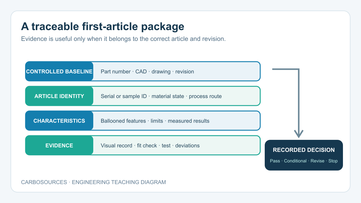
In a general industrial project, “first article” often means the first part evaluated against the controlled requirements before repeat production. It should not automatically be described as a formal aerospace First Article Inspection.
A practical carbon fiber first-article package may include:
- approved part number and revision;
- identified prototype or production-intent status;
- ballooned drawing or numbered characteristic list;
- nominal requirements, tolerance limits and measured results;
- material and process references required by the project;
- visual or finish record;
- fit-check or functional-test result;
- deviation and disposition record;
- approval status and date.
Formal AS9102 or another customer-specific FAI format applies only when required by contract or the relevant quality system. Its documentation should be prepared and approved by qualified parties. A generic blog checklist is not a substitute for that controlled requirement.
For CFRP prototype inspection, preserve the link between the measured article and the correct drawing, material state and manufacturing route. A report with accurate measurements can still mislead if it belongs to a different revision or a nonrepresentative process.
10. Decide Pass, Revise or Stop
Every prototype should end with a recorded decision. Useful outcomes are:
- Pass: The stated questions were answered and the controlled configuration may proceed to the next gate.
- Conditional pass: The result is usable, but listed corrections must be incorporated before release.
- Revise and repeat: The design, tool, process or inspection plan changes enough that another representative article is needed.
- Stop or redirect: The selected concept or route no longer supports the project requirement.
Avoid approving a sample by appearance while leaving dimensions, interfaces or deviations unresolved. Likewise, do not reject an entire concept because a geometry-only mockup failed a test it was never intended to represent.
When a change is accepted, update the controlling file rather than relying on email or verbal history. Record whether the change affects tooling, laminate, machining, inspection or previously completed validation.
Worked Example: Automation Mounting Plate
Consider a flat carbon fiber mounting plate for an automated inspection head. The initial CAD model contains the outer profile, four mounting holes and a central equipment pattern. The project needs a lightweight plate that aligns two assemblies and limits deflection during rapid motion.
Initial gaps
The model does not identify datums, the load from the inspection head, the required flatness, the plate’s fiber architecture or which hole pattern controls alignment. One pair of holes is also close to the free edge. Specifying only “2 mm 3K carbon fiber” would not resolve these issues.
Prototype question
The first article is defined to answer two questions: whether the mounting pattern assembles without interference and whether displacement at the equipment interface remains below the project limit under the stated fixture and load. Cosmetic finish is recorded but is not a pass criterion for this article.
Controlled inputs
The drawing establishes a primary mounting face, two datum holes and the measurement location for thickness and displacement. The team records the applied load, support points and equipment center of mass. Hole edge distance is reviewed, and one hole is moved before machining.
Prototype route
Because the geometry is flat and the immediate questions concern interface and stiffness, the prototype is machined from a controlled laminate rather than requiring a shaped mold. The drawing records laminate intent and the machining fixture uses the same datum concept as inspection.
First-article decision
The report compares every controlled feature with the drawing, records article weight and includes the defined deflection test. If assembly passes but displacement exceeds the limit, the next revision can address thickness, support spacing or laminate architecture. The result identifies the design variable to change instead of merely declaring that “carbon fiber was not stiff enough.”
One-Page Carbon Fiber Prototype Checklist
Use the following list as a final gate before releasing the prototype.
| Area | Checklist question |
|---|---|
| Purpose | Is the decision the prototype must support written clearly? |
| Representation | Are production-representative and simplified characteristics identified? |
| CAD | Is the controlling 3D model identified by revision and units? |
| Drawing | Are part number, revision, datums, dimensions and tolerances controlled? |
| Assembly | Are mating geometry, access and interface conditions available? |
| Loads | Are direction, magnitude, supports and relevant cycles defined? |
| Environment | Are temperature, moisture, UV, chemicals and metal contact considered? |
| Material | Are reinforcement, resin and permitted substitutions defined as needed? |
| Laminate | Are fiber direction, thickness and local reinforcement controlled? |
| DFM | Have drape, radii, draft, undercuts, transitions and demolding been reviewed? |
| Tooling | Is the tool level appropriate for the prototype question? |
| Machining | Are trim lines, holes, datums, fixtures and edge criteria defined? |
| Joining | Are insert, adhesive, fastener and clamp conditions documented? |
| Inspection | Can every acceptance requirement be measured with an agreed method? |
| Testing | Are fixture, load, duration, measurement and pass criteria defined? |
| First article | Are drawing characteristics, results and deviations traceable to the article? |
| Change control | Is responsibility for approving and recording changes clear? |
| Release | Is the outcome recorded as pass, conditional pass, revise or stop? |
A disciplined carbon fiber prototype checklist does not attempt to eliminate iteration. It makes each iteration informative. By controlling the question, design inputs, laminate intent, DFM review and acceptance evidence, the project can distinguish a fit model from a functional article and a promising sample from a process ready for repeat production.