
Home › Carbon Fiber Sheets › Carbon Fiber Sandwich Panels



CUSTOM LIGHTWEIGHT COMPOSITE PANELS
Custom Carbon Fiber Sandwich Panels and Sheets
Carbosources develops custom carbon fiber sandwich panels and carbon fiber sandwich sheets for OEM structures that need a large, stiff surface without the mass of a thick solid laminate. A sandwich panel combines two carbon composite face skins with a lower-density core, but the product cannot be defined by overall thickness alone. Skin construction, core type, support span, edge treatment and attachment details work together.
Send the panel envelope, load direction, mounting points, quantity and operating environment. We can then review whether the project should be quoted as uncut sheet stock, a near-net blank or a CNC-machined component with sealed edges and local hard points.
| Design input | What the drawing or RFQ should state |
|---|---|
| Panel envelope | Finished length, width and total thickness with units |
| Face skins | Material construction, layup intent, visible sides and surface finish |
| Core | Preferred core family, core thickness, density or performance requirement |
| Support and load | Mounting points, unsupported span, load direction and allowable deflection |
| Edges | Open edge, sealed edge, bonded closeout or locally reinforced perimeter |
| Machining | Cut profile, holes, slots, pockets, inserts and datum scheme |
| Environment | Temperature, moisture, chemicals, flame requirements and service location |
| Acceptance | Critical dimensions, flatness, appearance, bond quality and documentation |
A useful quotation separates requirements from preferences. For example, a maximum mass or deflection limit is more informative than asking for the lightest possible panel. If a core material is already specified, include the reason and the source standard. Material availability and suitability are confirmed during technical review rather than assumed from a generic product name.
For applications that do not need a lightweight core, compare the available carbon fiber sheet and solid laminate options before choosing the panel construction.
Define the Panel from the Load Path
Start with the load path. The face skins carry tension and compression when the panel bends, while the core keeps the skins separated and transfers shear. Increasing the distance between skins can improve bending rigidity, but the result still depends on skin stiffness, core shear properties, bond quality, support spacing and load introduction. This is why two carbon fiber sandwich sheets with the same total thickness may behave differently.
Show the unsupported span, boundary conditions and where loads enter the panel. Point loads from bolts, feet or brackets can crush a lightweight core unless the design includes a hard point, insert or locally reinforced region. Distributed pressure, impact and vibration also require different face-skin and core decisions.
For appearance-sensitive parts, identify the visible face or faces separately from the structural requirement. Woven, unidirectional and mixed layups do not provide the same directional behavior. The carbon fiber reinforcement comparison explains the basic differences, but the final laminate schedule must follow the actual load case.
Choose a Core for Carbon Fiber Sandwich Panels
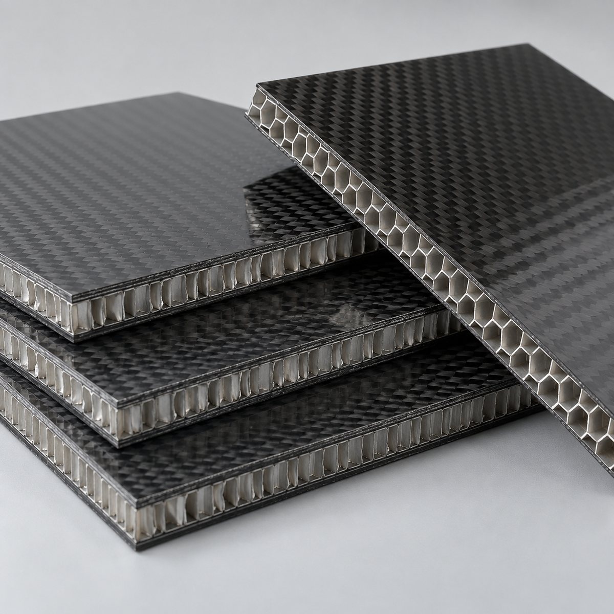
A carbon fiber honeycomb panel uses a cellular core that can provide high stiffness at low mass. The engineering review should consider honeycomb material, cell direction, density, core thickness, moisture exposure, edge sealing and how concentrated loads enter the panel. Open honeycomb cells at a cut edge normally require a defined closeout method before the part enters service.
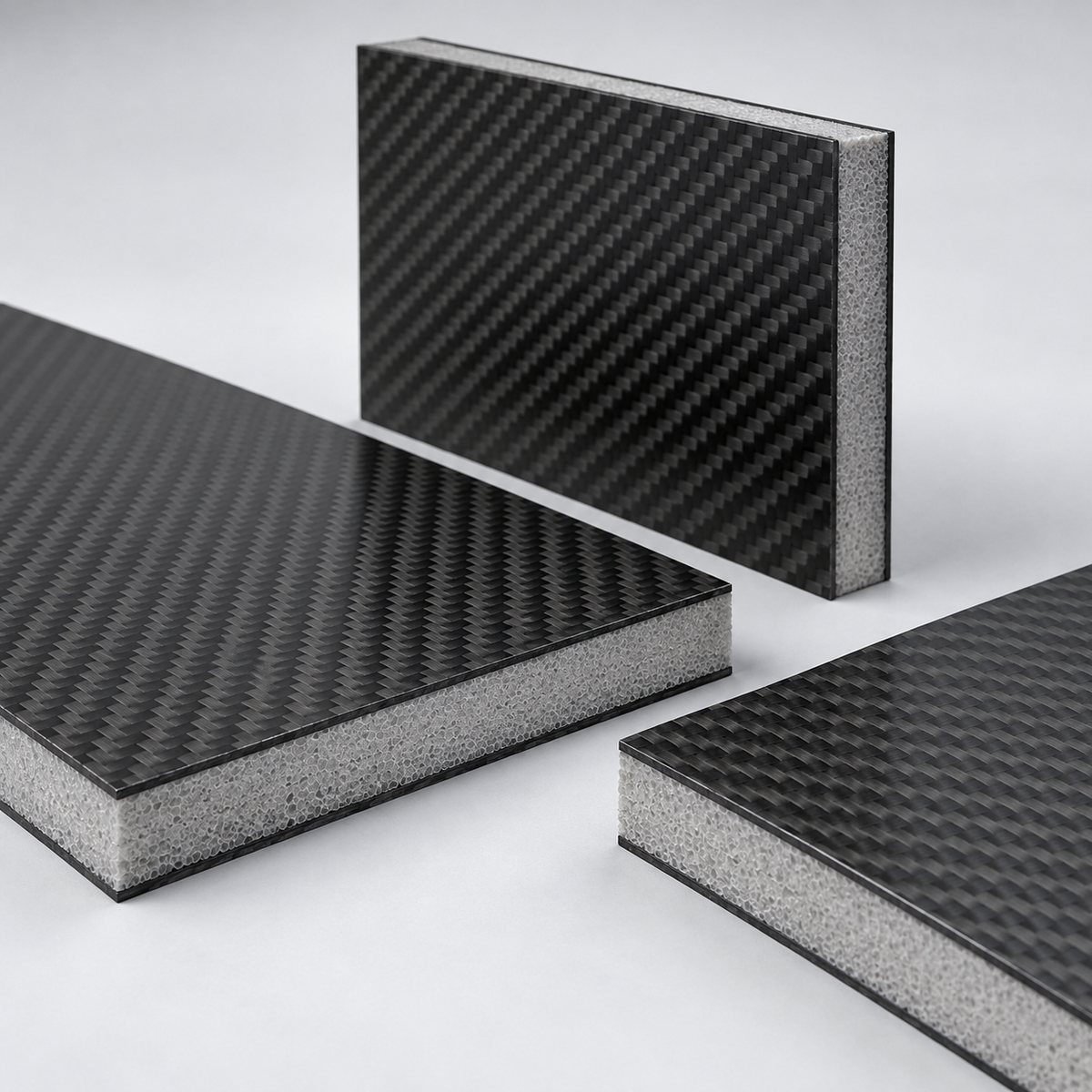
A carbon fiber foam core panel replaces the cellular core with structural foam. Foam family, density, temperature capability, moisture behavior, machinability and bond compatibility all matter. Foam may simplify shaped edges or local machining in some designs, while honeycomb may be preferred for other stiffness and mass targets. These are design choices, not interchangeable labels.
| Decision | Sandwich panel question | Why it matters |
|---|---|---|
| Core family | Honeycomb, structural foam or another approved core? | Changes shear behavior, local compression, moisture response and processing |
| Skin balance | Are both skins structurally balanced? | Influences flatness, warpage and directional response |
| Visible surface | Is one face cosmetic or are both faces visible? | Controls finish, handling and inspection criteria |
| Attachment | Bonded, bolted, inserted or framed? | Determines local reinforcement and edge-detail needs |
Core names alone do not establish performance. Ask for the material construction and available technical data. Carbosources confirms feasible core and skin combinations after reviewing the application.
CNC Machining, Edge Closeouts and Inserts
Machining a custom carbon fiber sandwich panel is different from trimming a solid carbon plate. A cut can expose the core, interrupt the bond line or create a weak region beside a fastener. The drawing should therefore show which edges remain open, which require sealing, and where solid closeouts or local reinforcement are needed.
For holes and slots, define the datum scheme, positional requirement and fastener interface. Threaded inserts or bonded hard points need enough surrounding support to transfer load into both face skins without crushing the core. Insert selection, preparation and adhesive process must be reviewed as part of the joint rather than added after panel manufacture.
CNC profiles, drilling and pocket features can be supplied from customer drawings when the construction is suitable. Include DXF for two-dimensional contours and STEP or IGES when the component contains three-dimensional details. The carbon fiber CNC machining service describes the drawing inputs used for machined composite components.
Typical uses include UAV and robotics platforms, automation bases, equipment covers, instrument panels, vehicle interior structures and other large lightweight surfaces. Application names do not replace engineering inputs: identify the span, support, loads, attachment method and service environment for each project.
What to Put on the Panel Drawing
- Geometry: finished length, width, total thickness, corner radii and cut profile.
- Skin definition: reinforcement type, layup intent, skin thickness or performance target.
- Core definition: preferred material, thickness, density or required behavior.
- Interfaces: bonded zones, fasteners, inserts, hard points, frames and mating parts.
- Edges: open, sealed, potted, capped or structurally closed.
- Appearance: visible sides, weave alignment, matte or gloss preference and protective film.
- Service conditions: temperature, moisture, chemicals, vibration and any required compliance.
- Inspection: critical tolerances, flatness, surface criteria and requested records.
If the design is at an early stage, provide target mass, load, allowable deflection and mounting concept instead of inventing a laminate. If the design is released, send the controlled drawing revision and bill-of-material notes. Prototype quantity and expected repeat volume should be stated separately so sampling, tooling, machining and inspection can be reviewed together.
For standard sheet stock, show the downstream cutting plan and minimum usable area. For ready-to-install parts, dimension all final features and note which surfaces must remain protected through shipping.
Inspection and Acceptance Criteria
Inspection should focus on features that affect function. Typical checkpoints include overall dimensions, total thickness, flatness where specified, face-skin appearance, edge condition, machining position and insert location. Bond-line and internal acceptance methods depend on the construction and project requirement; they should be agreed before production rather than added after the panels are complete.
A cosmetic carbon surface also needs written acceptance criteria. Weave shift, print-through, small resin-rich areas and handling marks do not have the same significance for a hidden structural face and a customer-facing panel. Define the viewing side, finish reference, lighting condition and acceptable protected area when appearance controls acceptance.
Packaging is part of quality control for large flat panels. State whether faces require protective film, interleaving or rigid support, and identify edges or inserts that cannot carry stacking load. For repeat orders, retain the approved drawing revision, material definition, finish reference and inspection plan so changes are controlled.
For repeat programs, carbon fiber sandwich panels should be controlled by the approved skin construction, core definition, edge detail, drawing revision and inspection plan rather than by overall thickness alone.
Send Your Carbon Fiber Sandwich Panel Requirements
Send the finished dimensions, preferred core, face-skin requirement, quantity, operating environment and drawing. Carbosources will review the panel construction, edge details, CNC features and inspection points before quotation.
Frequently Asked Questions
What is the difference between a sandwich panel and a solid carbon fiber sheet?
A sandwich panel separates thin structural skins with a lightweight core to increase section depth. A solid sheet is a continuous laminate. Selection depends on span, thickness allowance, local loads, machining and attachment requirements. See the carbon fiber sheet thickness guide for the limits of selecting material by thickness alone.
Can carbon fiber sandwich panels be CNC machined?
Yes, when the core, skin and edge details are considered in the machining plan. Exposed cores, fastener zones and inserts require defined treatment.
Should I choose honeycomb or foam core?
Choose from the load path, local compression, temperature, moisture, impact, machining and mass requirements. A preferred material can be reviewed, but the project data should drive the choice.
Can both faces be cosmetic?
Two visible faces can be reviewed. State the finish, weave alignment, protection and acceptance criteria for each side.
What information is needed for a quote?
Provide dimensions, total thickness, quantity, preferred skin and core, visible sides, edge treatment, drawing, attachments, service environment and critical tolerances.