
Home › Carbon Fiber Tubes › Roll Wrapped Carbon Fiber Tubes


PREPREG TUBES SPECIFIED FROM THE LOAD PATH AND INTERFACES
Custom Roll Wrapped Carbon Fiber Tubes
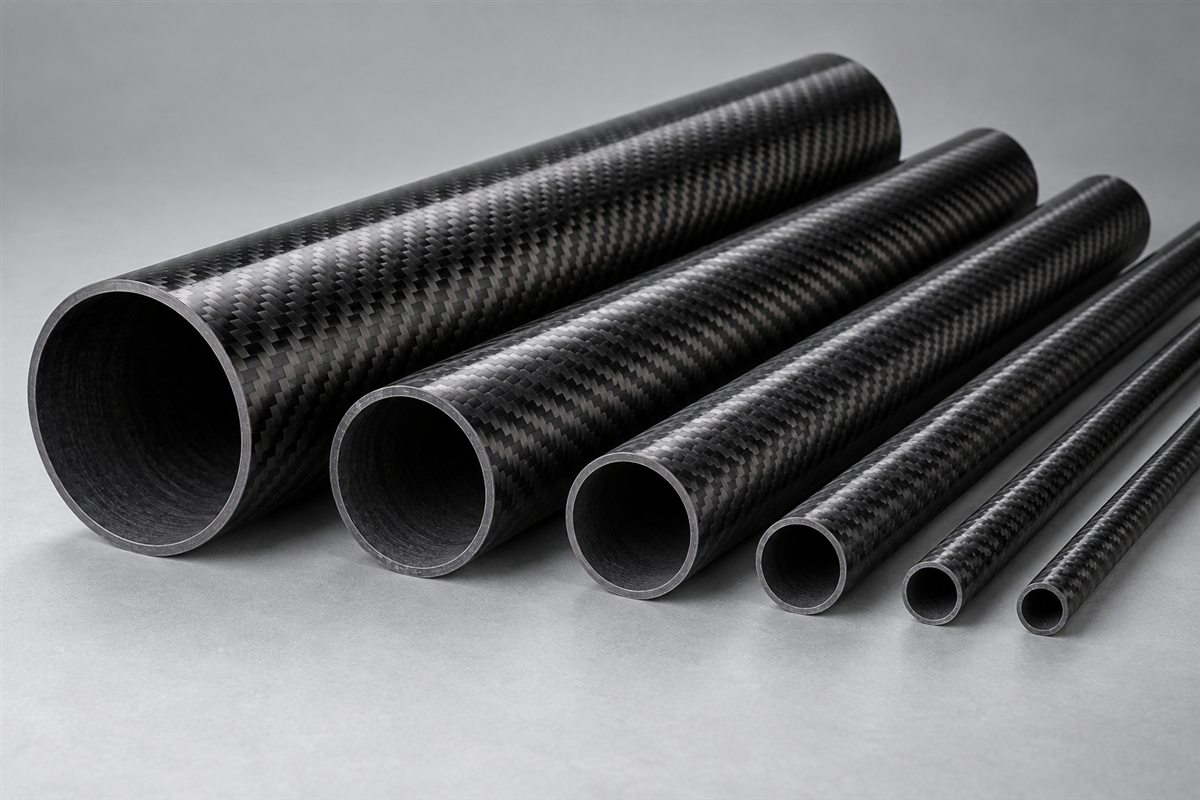
Carbosources develops custom roll wrapped carbon fiber tubes for OEM structures that need project-specific diameter, wall construction, fiber orientation and surface finish. Prepreg plies are wrapped around a mandrel and consolidated into a tubular laminate, allowing the reinforcement package to be reviewed around bending, axial, torsional and local interface loads.
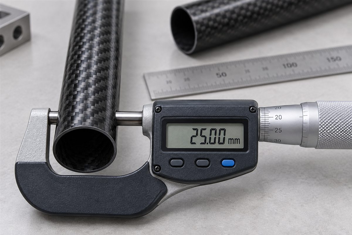
A useful request defines more than “3K carbon tube.” Send the critical OD or ID, wall requirement, finished length, load directions, mating parts, machining features, quantity and operating environment. These inputs allow the roll wrapped carbon fiber tube, secondary processing and inspection requirements to be considered as one component.
| Specification input | What the RFQ or drawing should define |
|---|---|
| Critical diameter | State whether OD, ID or both control the interface and identify the mating part |
| Wall and length | Nominal wall thickness, usable length, finished cut length and end condition |
| Load case | Axial load, bending, torsion, shear, compression, impact, vibration and duty cycle |
| Reinforcement intent | Required stiffness direction, preferred construction or performance target |
| Surface | Natural wrapped, matte, satin, glossy, painted or cosmetic woven outer ply |
| Machining | Cutting, drilling, slots, flats, bonded inserts and datum-controlled features |
| Environment | Temperature, moisture, chemicals, UV exposure and electrical considerations |
| Acceptance | Diameter, straightness, roundness, length, appearance and requested testing |
Separate functional requirements from preferences. A customer may prefer a twill surface, but the internal structure still has to follow the load path. Likewise, a nominal wall thickness does not establish bending stiffness unless diameter, fiber orientation and material system are also known. Carbosources confirms feasible construction and tolerance options after reviewing the drawing rather than assigning one universal specification to every tube.
Start with the Critical Diameter and Load Path
In a roll-wrapping process, the tube is built around a mandrel. The mandrel therefore provides the starting geometry for the bore, while the laminate build, compaction and finish contribute to the final outside diameter. This distinction matters when the tube slides over an internal shaft, receives a bonded insert, fits inside a bearing or is clamped on its outer surface.
If the ID controls the assembly, identify the required fit and insertion length. If the OD controls a bearing, sleeve or clamp, identify the contact length and permitted clearance. Requiring tight OD, ID and wall tolerances simultaneously may require a different tooling and finishing plan. The carbon fiber tube sizing guide explains why dimensions should be connected to the actual interface.
Tube length also depends on the available mandrel and processing route. Long parts require attention to straightness, extraction and shipping support. When a one-piece length is impractical, an internal sleeve, external ferrule or sectional assembly may be reviewed. A joined tube must be specified from its load path and envelope; simply extending two pieces with a short connector does not establish structural performance.
Choose the Layup and Surface for the Function
Custom prepreg carbon fiber tubes can combine reinforcement directions within one tubular laminate when the application requires more than a mainly longitudinal construction.
The main structural plies may use unidirectional or multidirectional prepreg according to the load case. Fibers close to the tube axis contribute strongly to axial and bending stiffness. Off-axis reinforcement can help carry torsion and shear, while circumferential restraint can support tube shape and local interfaces. The required balance depends on loading, diameter, wall and attachment details.
A woven 3K outer ply can provide handling support and a recognizable carbon appearance, but the visible weave alone does not define the laminate. Two roll wrapped carbon fiber tubes with the same twill surface and dimensions may have different internal reinforcement and therefore different structural behavior.
| Surface option | What it changes | Points to specify |
|---|---|---|
| Natural wrapped surface | Retains process texture with limited finishing | Allowed ridges, resin appearance and handling requirements |
| Ground or sanded matte | Creates a smoother low-gloss surface and may support OD control | Machining allowance, final OD and cosmetic criteria |
| Clear-coated gloss | Provides a smooth reflective cosmetic finish | Coating build, visible weave, UV requirement and allowable defects |
| Woven cosmetic ply | Changes the visible pattern and surface behavior | Plain or twill weave, alignment and visible side |
| Painted finish | Provides color or additional surface protection | Color reference, coating system and masked interfaces |
Surface finishing can change dimensions. Mark bearing seats, bonding areas, sliding fits and cosmetic zones separately so one global finish note does not create conflicting requirements.
When Roll-Wrapped Construction Makes Sense
A prepreg carbon fiber tube should be selected from the required stiffness and load directions. Pultruded tube is often efficient for predominantly longitudinal requirements and continuous production, while roll-wrapped construction offers more freedom to combine reinforcement directions and wall builds. Filament-wound and braided constructions provide other fiber paths and processing advantages. The correct route depends on geometry, volume, load and finish.
For a practical comparison, see the pultruded carbon fiber tubes page and the existing braided versus roll-wrapped tube guide. The product drawing should describe the performance requirement rather than choosing a process name from appearance alone.
Common applications include UAV and robotics members, automation frames, inspection booms, lightweight equipment shafts, instrument structures and sports-equipment components. A wing tube, torque tube or long beam can use similar material but has a different load and interface problem. Application names should lead to a controlled specification, not a copied stock size.
If mass is critical, provide the maximum allowable component mass together with stiffness and load requirements. Reducing wall thickness without considering buckling, local clamping and machining can move the failure risk to the interface.
What to Put on the Tube Drawing
- Geometry: critical OD, ID, wall thickness, length, end condition and allowable mass.
- Mating parts: bearings, sleeves, clamps, inserts or shafts with their fit requirements.
- Loads: bending moment, torque, tension, compression, side load, impact and duty cycle.
- Stiffness: allowable deflection, torsional rotation or other functional target.
- Surface: natural, matte, satin, glossy, painted or woven cosmetic requirement.
- Machining: holes, slots, flats, cutouts, countersinks and protected bond zones.
- Environment: temperature, moisture, chemicals, outdoor exposure and maintenance.
- Acceptance: dimensions, straightness, roundness, appearance, sampling and requested tests.
Provide a dimensioned PDF with drawing revision. DXF is useful for two-dimensional hole and slot patterns; STEP or IGES helps define inserts, clamps and complete interfaces. Identify functional datums and critical tolerances instead of applying one tight tolerance to every dimension. For secondary processing, review the carbon fiber CNC machining service.
Drilling and slotting interrupt fibers and create edge stresses. Bonded inserts introduce a short rigid load-transfer zone. The design review may consider feature position, edge distance, local reinforcement, insert length, bond gap and machining sequence. Threads should normally be provided by suitable fittings rather than cut directly into a thin composite wall.
Machining, Inspection and Qualification
Inspection should follow the function of the part. Typical checks may include OD, ID, wall, finished length, straightness, roundness, end-face condition, hole position and visible surface criteria. A tube intended for rotation may also need a defined runout setup, while a sliding fit needs inspection over the functional contact length.
If mechanical qualification is required, specify the test mode, fixture, loading direction, sample quantity and acceptance value before prototypes are built. Flexural, torsional, compression and insert pull-out tests address different failure modes. Test results from another diameter or laminate should not be treated as a rating for the new component.
Packaging is part of dimensional protection for long or thin-wall tubes. State whether cosmetic surfaces require film or interleaving and whether the tube ends need plugs or rigid support. Protruding inserts and machined edges should not carry stacking load during transport.
For repeat orders, retain the approved drawing revision, construction definition, finish reference and inspection plan. Changes to fiber orientation, prepreg, cure route, finish or machining can affect performance even when the nominal dimensions remain the same.
Send Your Roll Wrapped Tube Requirements
Send the tube drawing, critical OD or ID, wall and length, load directions, surface requirement, mating components, quantity and requested inspection. Carbosources will review the rolled carbon fiber tubing, tooling, machining and acceptance requirements before quotation.
Frequently Asked Questions
What is a roll wrapped carbon fiber tube?
It is a tubular laminate made by wrapping prepreg plies around a mandrel, consolidating and curing them, then completing the required trimming and finishing.
Does 3K twill define the strength of the tube?
No. It normally describes a tow size and visible weave. Internal fiber orientation, material system, diameter and wall construction control structural behavior.
Should I specify OD or ID?
Specify the dimension that controls the mating interface and provide the mating component. If both are critical, state their functions and tolerance priorities.
Can roll-wrapped tubes be drilled or fitted with metal inserts?
These features can be reviewed from the drawing. Hole position, local reinforcement, insert geometry, bond area and machining sequence should be considered before manufacture.
What information is needed for a quote?
Provide dimensions, mating fits, loads, stiffness target, surface, machining, quantity, environment, drawing files and required inspection or testing.