
Home › Carbon Fiber Tubes › Tapered Carbon Fiber Tubes


VARIABLE-DIAMETER COMPOSITE TUBES DEFINED FROM GEOMETRY, LOADS AND END INTERFACES
Custom Tapered Carbon Fiber Tubes
Carbosources develops custom tapered carbon fiber tubes for OEM structures that need a larger, stiffer root and a lighter free end. A finished tapered carbon fiber tube is defined by its large-end diameter, small-end diameter, taper length, wall construction, fiber orientation and interfaces—not by overall length alone.
Projects are reviewed from customer drawings for UAV structures, marine spars, automation booms, inspection equipment and other lightweight members. Send the actual support span, load direction, allowable deflection, mating components, surface requirement and quantity. These inputs allow the tapered geometry, tooling, laminate and secondary operations to be considered together before quotation.
| Design input | What the RFQ or drawing should define |
|---|---|
| Large end | Critical OD and ID, straight land length, mating part and required fit |
| Small end | Critical OD and ID, minimum wall, trimming condition and attached hardware |
| Taper | Overall length, effective taper length, taper angle or diameter change between controlled stations |
| Wall construction | Nominal wall, variable-wall intent, reinforcement directions or performance target |
| Loads | Bending, axial load, torsion, compression, side load, vibration, impact and duty cycle |
| Interfaces | Clamps, sleeves, threaded inserts, bonded fittings, holes, slots and bond zones |
| Environment | Temperature, moisture, chemicals, UV exposure and contact with dissimilar metals |
| Acceptance | Measurement stations, straightness, surface, mass and requested mechanical or joint tests |
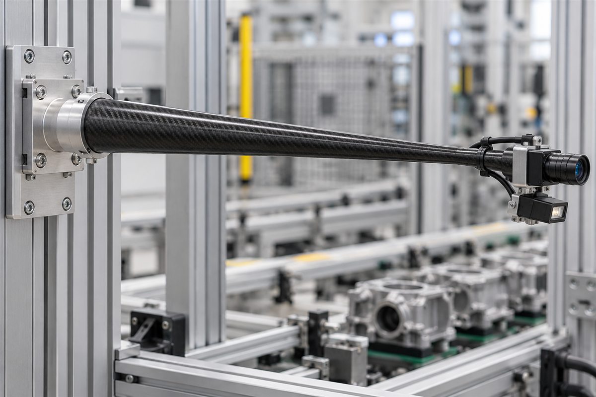
A useful specification connects each dimension to a function. The large end may fit a mounting block while the small end carries a camera, sensor or aerodynamic component. If both interfaces are critical, identify their contact lengths and tolerance priorities. Carbosources confirms feasible tooling and manufacturing options after reviewing the drawing; one generic size or performance rating does not apply to all tapered carbon fiber tubing.
Define the Large End, Small End and Taper
Start with the two controlled ends and the stations between them. Define the large-end OD and ID, small-end OD and ID, overall length and the length over which the diameter changes. A short constant-diameter land may be needed for clamping, bonding or bearing contact. Show whether the taper continues to the trim line or stops before an end fitting.
A nominal taper angle is not enough when the assembly uses several contact points. Add section dimensions at functional stations along the tube. For a conical carbon fiber tube, state whether the OD, ID or both must follow the cone. Tight OD and ID control together can require a different tooling or finishing plan, especially when wall thickness also changes.
| Geometry | Useful when | Important review points |
|---|---|---|
| Constant-taper round tube | A straight member reduces continuously from root to tip | Mandrel extraction, end lands, controlled diameter stations and wall build |
| Stepped-diameter tube | Different interfaces need distinct cylindrical sections | Transition radii, local stress, tooling split and machining allowance |
| Variable-wall tapered tube | Mass distribution is optimized along the span | Ply drops, minimum wall, laminate continuity and inspection plan |
| Tapered oval or shaped tube | Directional stiffness or installation envelope controls the section | Major/minor axes, section clocking, twist and dedicated tooling |
A tapered tube is not a telescopic tube. A taper changes diameter along one continuous member; a telescopic assembly uses separate tubes that slide or lock together. See the carbon fiber telescopic tubes page when adjustable length is the primary function.
Match the Laminate to Bending and Torsion
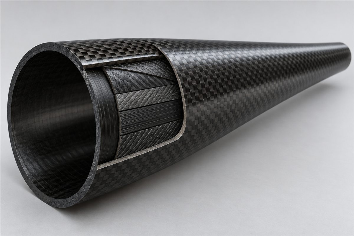
The laminate must follow the actual load path. Fibers near the tube axis contribute strongly to axial and bending stiffness. Off-axis reinforcement helps carry torsion and shear, while circumferential restraint supports tube shape and local clamping. The appropriate balance changes with taper ratio, wall, span, load direction and the way each end is supported.
The large end often carries the highest bending moment in a cantilever, but the small end can become vulnerable to local crushing, trimming damage or an abrupt fitting. A cosmetic woven outer ply does not define structural performance. Two tapered carbon tubes with the same visible weave and end diameters may behave differently because their internal reinforcement and interfaces differ.
| Requirement | Drawing or engineering input | Why it matters |
|---|---|---|
| Bending stiffness | Support span, load position, tube orientation and allowable deflection | Controls axial reinforcement and section distribution |
| Torsional stiffness | Applied torque, allowable rotation and duty cycle | Supports selection of off-axis reinforcement |
| Local clamp load | Clamp width, bolt preload concept and contact surface | Identifies crush risk and possible local reinforcement |
| End fitting | Insert or sleeve geometry, insertion length, shoulder and bond gap | Defines the load-transfer region |
| Mass target | Maximum finished mass together with stiffness and strength needs | Prevents weight reduction from overriding interface reliability |
Plan Tooling, Demolding and End Interfaces
A tapered mandrel can provide the internal geometry, but the finished part also depends on material placement, compaction, cure, release and extraction. The small end, total length and taper angle influence whether the cured tube can be removed without damaging the laminate or tool. Long shallow tapers may need special extraction planning, while abrupt transitions can concentrate strain and complicate consolidation.
Existing tooling is normally the economical starting point for prototypes. A new large-end diameter, small-end diameter, taper length or shaped section may require a dedicated mandrel or mold and a suitable production quantity. Carbosources should review tooling ownership, sampling, expected tool life and dimensional verification before treating a drawing as production-ready.
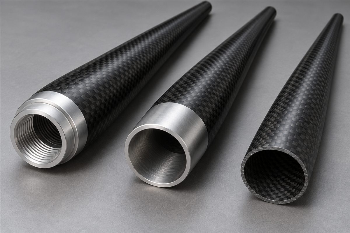
Design end interfaces before the laminate and tool are released. A cylindrical land can provide a predictable surface for a clamp, sleeve or bonded fitting. Threads are normally carried by a suitable metal insert rather than cut directly into a thin composite wall. The assembly drawing should define insert material, bond diameter, bond length, shoulder location, adhesive gap and how service torque enters the part.
Holes and slots interrupt fibers and create edge stresses. Show their position from a controlled datum and provide edge distance, fastener geometry and load direction. Possible responses include relocating a feature, adding a local reinforcement zone or using an external clamp. Related end-interface guidance is available on the carbon fiber tube assemblies page, while drawing-based secondary operations can be reviewed through carbon fiber CNC machining.
What to Put on the Tapered Tube Drawing
- Geometry: large-end OD/ID, small-end OD/ID, overall length, taper length, end lands and intermediate stations.
- Taper definition: angle, ratio or controlled diameters with axial locations and datum direction.
- Loads: bending moment, tension, compression, torque, side load, vibration, impact and duty cycle.
- Stiffness: allowable tip deflection, torsional rotation or other functional target.
- Interfaces: clamps, sleeves, bearings, inserts, threaded hardware, bond zones and mating-part drawings.
- Machining: finished cuts, holes, slots, flats, trim angles and protected surfaces.
- Environment: temperature, moisture, chemicals, UV exposure and electrical isolation.
- Acceptance: measurement stations, straightness, appearance, mass, sampling and requested tests.
Provide a dimensioned PDF with drawing revision. STEP or IGES helps define the full conical surface, inserted hardware and surrounding assembly; DXF can support hole and slot patterns. Identify functional datums and critical tolerances instead of assigning one tight tolerance to every dimension. If the tube carries a moving payload, include the assembly mass and center of gravity.
For an early feasibility review, a table of axial stations and target diameters is often clearer than a sketch alone. State whether dimensions apply before or after sanding, coating or other finishing. If the requirement is primarily a straight constant-diameter prepreg tube, compare the existing roll wrapped carbon fiber tubes page before specifying custom taper tooling.
Inspection, Qualification and Packaging
Inspection should follow the controlled geometry. Typical checks can include end diameters, diameter at intermediate stations, finished length, end squareness, wall at accessible sections, straightness, visible surface criteria and the angular position of machined features. When a shaped taper is used, major/minor axes and section twist may also need defined measurement methods.
If mechanical qualification is required, specify the test before prototypes are built. Flexural, torsional, compression, insert pull-out and proof-load tests evaluate different failure modes. Define the fixture, support span, loading direction, load level, hold time, sample quantity and acceptance value. Test data from another taper or laminate should not be treated as a rating for the new component.
Typical applications include UAV booms and wing structures, marine masts, automation and robotics arms, camera or inspection booms, lightweight equipment supports and OEM sporting structures. Application names are only starting points: each project still requires its real span, load, support, interfaces and environment.
Long or thin-wall tubes should be supported during transport so the small end does not carry stacking or impact load. State whether cosmetic surfaces require film, interleaving or rigid cradles and whether protruding fittings need individual protection. For repeat orders, retain the approved tool reference, drawing revision, laminate definition, finish standard and inspection plan.
Send Your Tapered Tube Requirements
Send the tube drawing, large-end and small-end diameters, taper and overall lengths, wall or performance target, loads, end interfaces, quantity and requested inspection. Carbosources will review the custom tapered carbon fiber tube, tooling, laminate, machining and acceptance requirements before quotation.
Frequently Asked Questions
What is a tapered carbon fiber tube?
It is a continuous composite tube whose section changes from a larger end to a smaller end along part or all of its length.
Can you manufacture a custom taper from my drawing?
Custom geometry can be reviewed from controlled end diameters, taper length, intermediate stations, wall requirements, loads and quantity. New geometry may require dedicated tooling.
What is the difference between a tapered and telescopic carbon tube?
A tapered tube is one continuous variable-diameter member. A telescopic assembly uses separate nested tubes to change length.
Can a tapered tube include metal inserts?
Bonded inserts, sleeves and threaded interfaces can be reviewed when fit, insertion length, bond geometry, loads and qualification requirements are defined.
What information is needed for a quote?
Provide the drawing, controlled diameters, lengths, wall or stiffness target, loads, mating parts, machining, finish, quantity, environment and requested inspection.