How the Process Shapes the Tube
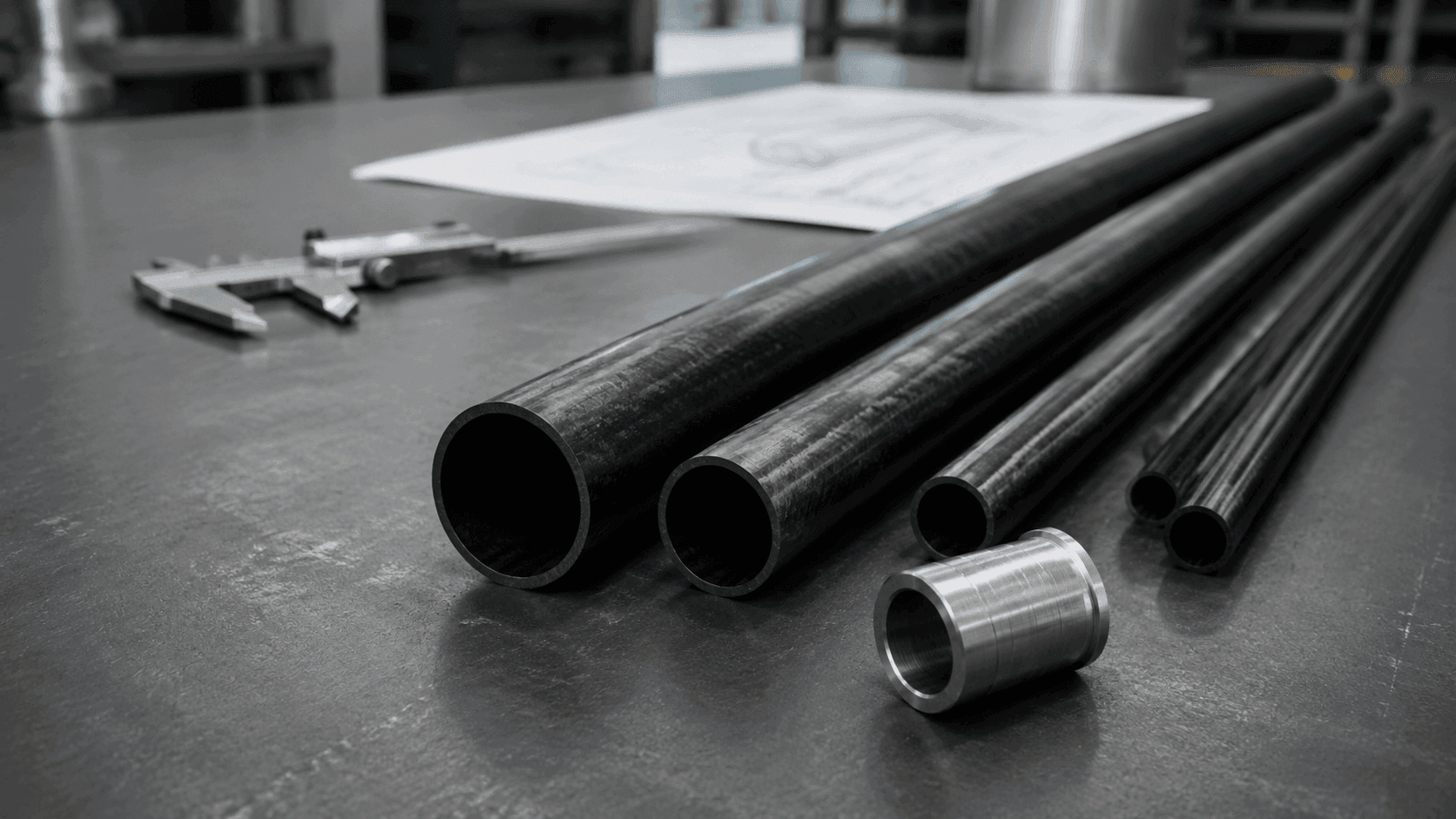
Pultruded carbon fiber tubes are formed by pulling continuous carbon fiber tows through a resin bath and then through a heated die, where the material cures while still being drawn forward. Because the fibers travel straight through the die rather than being wound or braided, they end up aligned almost entirely along the tube's axis. That orientation is what gives the tube its pronounced longitudinal stiffness. A design dominated by axial tension, compression, or bending along the tube's length can take real advantage of carbon fiber's directional strength, and this axial alignment is the main reason engineers reach for the pultrusion process when stiffness along one direction matters more than performance in every direction at once.
Longitudinal Strength Against Radial Weakness
The same alignment that produces strong longitudinal stiffness leaves almost no hoop fibers running around the tube's circumference. Without that reinforcement, the wall tends to resist localized compression and impact loads poorly, and a sharp point load or a dropped tool can crack or crush the wall rather than simply dent it. Roll-wrapped tubes include some fiber oriented around the hoop direction, which tends to give them better radial compression resistance, though they generally fall short of the longitudinal rigidity that straight pultrusion achieves. Neither construction is better in every sense; the right choice depends on whether the dominant load path in service is axial or radial, and that question is worth settling before a tube type is fixed on paper rather than after fabrication has already begun.
Matching the Method to the Load Case
Because pultruded carbon fiber tubes trade radial capability for longitudinal performance, the selection decision really comes down to how well the expected load case has been defined. A project with a clear, mostly axial load path benefits from committing to pultrusion early, since redesigning around a different fiber architecture later is costly. A project with mixed or uncertain loading, on the other hand, may be better served by gathering more detailed load data before specifying either construction, rather than defaulting to whichever tube type is easiest to source on short notice.
Internal Pressure Service
Internal pressure service is a clear limitation for pultruded carbon fiber tubes. With little to no fiber running around the hoop direction, the wall offers limited resistance to pressure pushing outward, and sustained or repeated internal pressure can lead to cracking or splitting over time rather than a clean, predictable failure. These tubes should be avoided in pneumatic lines, hydraulic passages, or other sealed, pressure-containing structures. Where a design calls for internal pressure, a construction that includes circumferential reinforcement is typically the safer starting point, or the layout should be revised so the tube itself is never asked to hold pressure on its own.
Making Reliable Connections
Connections tend to be where pultruded carbon fiber tubes cause the most trouble in practice, largely because the same axial fiber path that gives the tube its stiffness also makes it sensitive to anything that interrupts it. Bonding a metal insert to the inside or outside of the tube with structural adhesive is the approach most often recommended, since it keeps the fiber path intact and avoids cutting into it. Drilling through-holes, adding through-bolts, or applying uneven clamp force can disrupt the fiber layout and create stress concentrations that raise the risk of splitting near the tube end. Surface preparation has a strong influence on bond quality: the bonding area should stay clean and dry, and any abrasion should remain shallow enough that the surface fibers stay intact rather than being cut through in the process.
Clamping and Assembly
Mechanical clamping has real limits on these tubes. Even with rubber pads or a flexible sleeve, high clamping force can still crush the wall, since there is little radial fiber support to resist it once local pressure builds up at a single point. Where clamping cannot be avoided, positioning the clamp over a pre-bonded metal sleeve is usually a safer approach than clamping the bare carbon fiber tube directly. For joints that need to come apart later, an inserted metal fitting secured with structural adhesive and then threaded on its own is generally preferable to cutting threads straight into the composite wall, which would sever fibers at exactly the point where load is concentrated.
Where These Tubes Are Typically Used
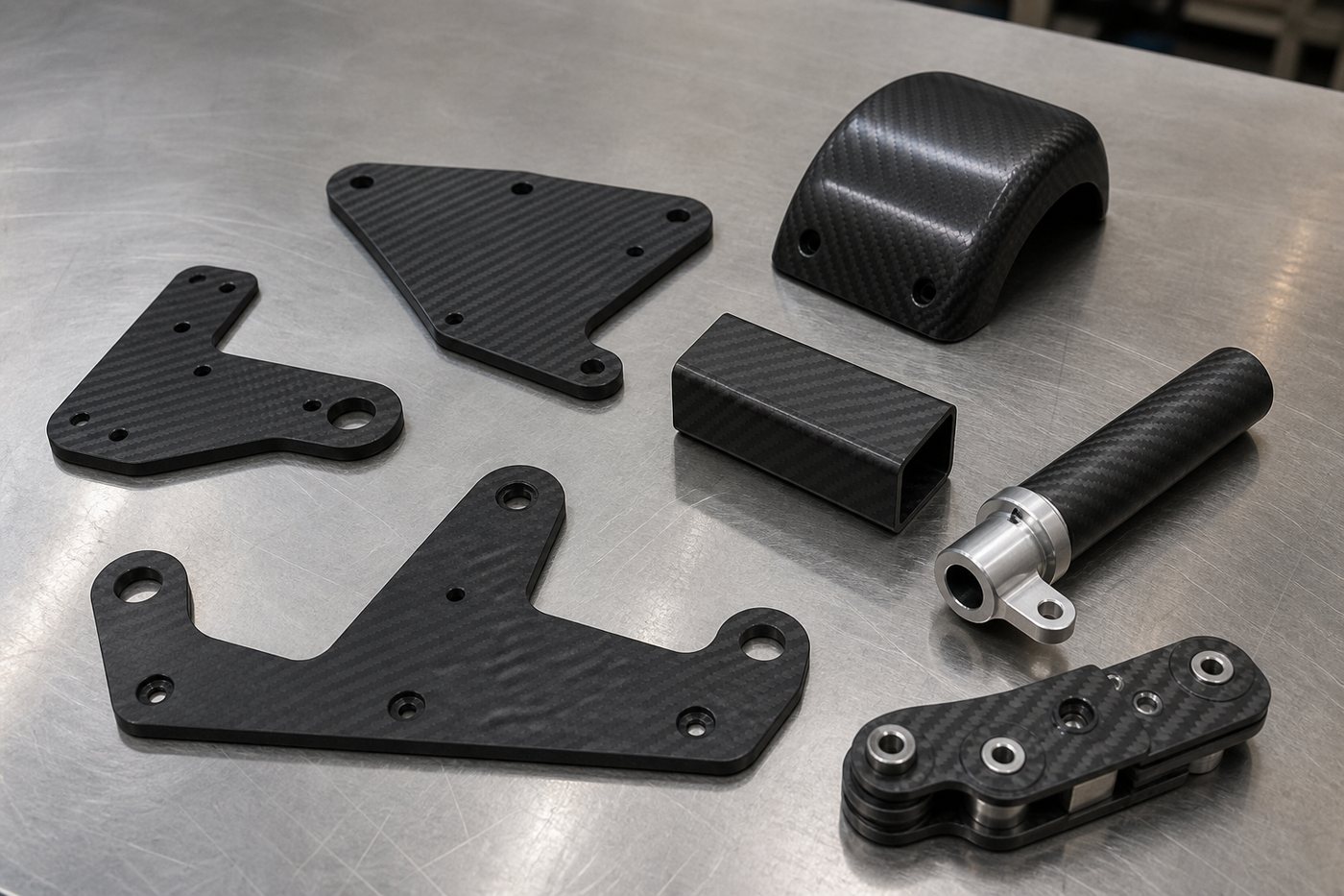
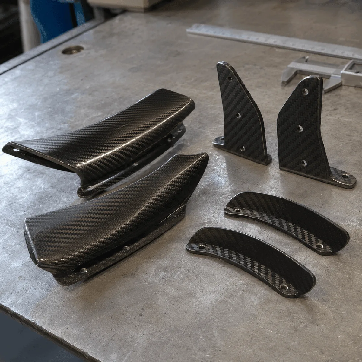
Reported applications for pultruded carbon fiber tubes include drone arms, multirotor frames, model aircraft components, automation equipment parts, leisure gear, and certain racing vehicle parts. What these examples have in common is a need for high longitudinal stiffness at low weight, a reasonably predictable load path, and little to no radial force in service. In cases like these, the performance profile of a pultruded tube tends to line up well with the requirement. That said, matching a tube to an application category is only a starting point; the specific load case in a given project still needs its own verification rather than an assumption carried over from a similar-sounding use elsewhere.
Questions to Confirm Before Selection
Before settling on a tube, a few questions are worth working through directly with the supplier rather than assuming a favorable answer. Are the governing loads primarily axial tension and compression or bending, with internal pressure and significant radial squeezing ruled out for this application? Does the connection design rely on bonded metal inserts, with surface preparation and cure time handled according to the adhesive supplier's own instructions? Has the supplier shared measured data on fiber volume fraction, resin system, and longitudinal modulus, rather than only nominal or catalog values? At clamping or assembly points, has local compressive stress been checked against the wall's capacity, with padding added to avoid a hard point contact? If the service environment involves elevated temperature, humidity, or chemical exposure, has resin compatibility with those specific conditions been confirmed directly with the supplier?