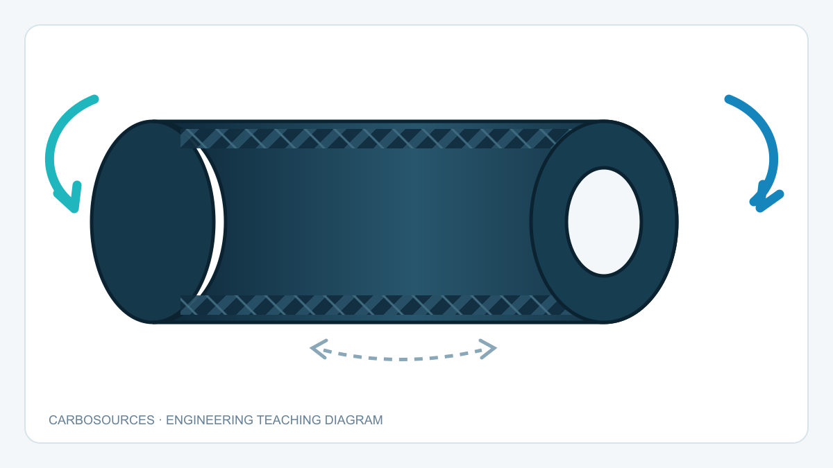
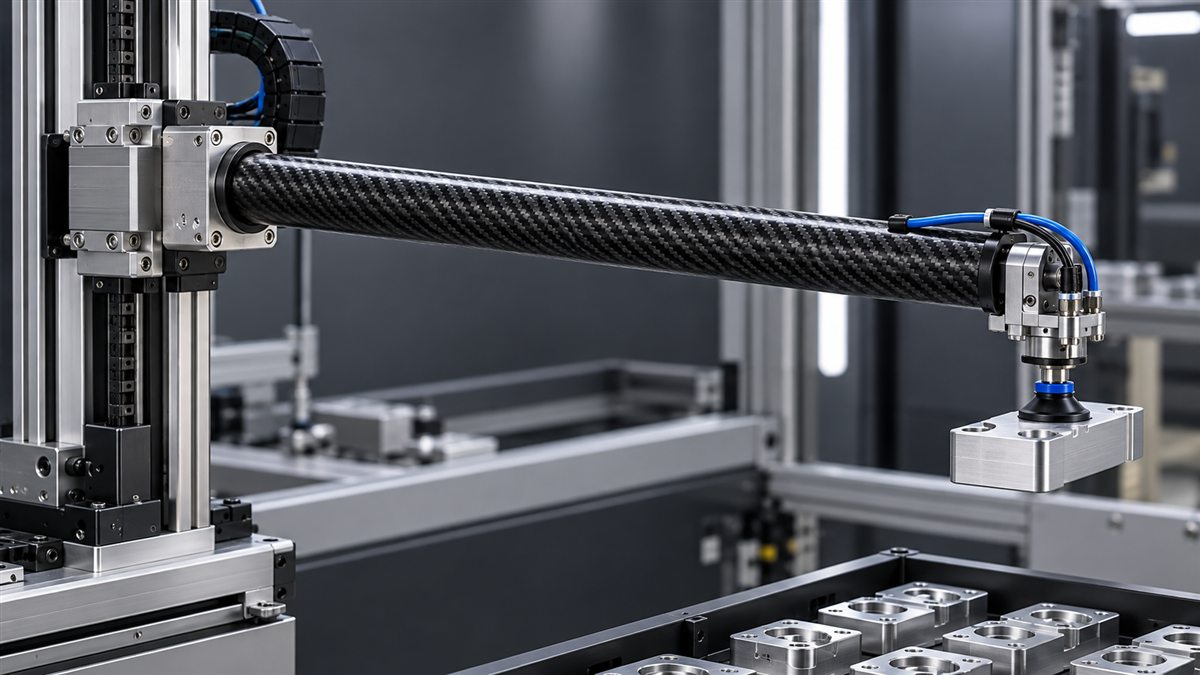
A pick-and-place arm does more than carry a payload. It must accelerate, stop and hold the end effector inside a positioning tolerance. A tube can be strong enough to avoid failure and still be too flexible for the required cycle. It can also meet a static deflection limit yet continue to oscillate after every move.
That is why carbon fiber tubes for pick-and-place systems should be selected by stiffness and dynamic behavior as well as strength. Carbon fiber tube vibration becomes a separate design limit when residual motion delays the next pick or placement. Span, payload position, section geometry, laminate orientation, end fittings and mounting conditions all influence what happens at the tool point.
This guide explains how to separate static deflection from vibration and settling time, how to make useful first-pass calculations, and how to validate a carbon fiber automation beam without treating a material datasheet as a finished-component specification.
Start with the Performance Requirement at the Tool Point
The useful requirement is normally expressed at the gripper, suction cup, camera or dispensing head—not at the middle of the tube. Before choosing a tube, define what the machine must do at that location.
Record at least:
- The unsupported span and the actual support condition.
- The moving mass of the end effector, mounting plate, sensors, valves, cables and workpiece.
- The payload center of gravity relative to the tube axis and support.
- The maximum static displacement allowed at the tool point.
- The motion profile, including acceleration, deceleration and emergency-stop cases.
- The allowable time for residual motion to enter the positioning band.
- The main bending direction, secondary bending direction and applied torque.
- The number of operating cycles and relevant temperature or humidity exposure.
These inputs separate a structural requirement from a general request for a “strong carbon fiber tube.” A tube that works for a slow inspection axis may not work for a high-acceleration transfer arm of the same length and payload.
Static Deflection, Vibration and Settling Time Are Different

These terms describe related but different behaviors.
| Term | What it describes | Typical machine effect |
|---|---|---|
| Static deflection | Displacement under a steady load | A consistent tool-point position offset |
| Dynamic deflection | Displacement while the structure accelerates or decelerates | A temporary error during motion |
| Natural frequency | A frequency at which the structure tends to oscillate | Sensitivity to resonance and motion-profile excitation |
| Damping | The rate at which vibration energy decays | How quickly oscillation reduces after a move |
| Settling time | Time required for residual motion to remain inside the allowed position band | Delay before the next operation can begin |
A low static deflection does not guarantee a short settling time. Conversely, a structure may have useful damping but still deflect too far under its payload. The tube, joints, drive system and control profile must be considered together.
A First-Pass Carbon Fiber Tube Deflection Calculation
For an ideal uniform cantilever with a point load at the free end, the familiar small-deflection beam equation is:
δ = FL³ / 3EI
where:
- δ is free-end deflection.
- F is the transverse end load.
- L is the cantilever length.
- E is the effective bending modulus in the relevant direction.
- I is the second moment of area of the section about the bending axis.
The equation is useful because it shows the relative influence of each design variable. Deflection changes linearly with load, inversely with bending stiffness EI, and with the cube of length. If the same beam becomes 20% longer while the other terms remain unchanged, the idealized deflection factor becomes 1.2³, or 1.728. This is a scaling comparison, not a prediction of the finished machine.
For a concentric circular tube:
I = π(D⁴ − d⁴) / 64
where D is outside diameter and d is inside diameter. Because diameter appears to the fourth power, moving material farther from the neutral axis can improve bending stiffness efficiently. This is why increasing outside diameter can sometimes reduce deflection more efficiently than adding the same mass as extra wall thickness.
These equations have limits. A real pick-and-place arm may include distributed mass, an offset payload, two-axis bending, torsion, flexible joints or a support that is not perfectly fixed. Carbon fiber is also anisotropic, so the correct effective bending stiffness depends on the laminate rather than a single generic value for “carbon fiber.” Use the beam equation to screen concepts, then validate the assembled structure.
How Span, Payload and Offset Change the Load Case
Span has a cubic influence in the ideal beam model
Small increases in unsupported length can create large increases in calculated deflection. Before increasing wall thickness, check whether the bearing spacing, clamp position or machine architecture can reduce the effective span.
The complete moving mass matters
The workpiece may be only part of the end load. A vacuum manifold, tool changer, camera, cable carrier and metal adapter can equal or exceed the payload mass. Leaving these items out of the model gives an optimistic result.
An offset center of gravity introduces a moment
If the payload acts away from the tube centerline, it can add bending and torsion. The tube may therefore need stiffness in more than one direction, and the end fitting must transfer the same moment without local rotation.
Acceleration creates inertial load
During motion, the structure must carry forces associated with accelerating its own mass and the attached equipment. A static weight calculation alone does not represent a rapid stop or reversal. Use the intended motion profile when defining the design load cases.
Tube Geometry: Diameter, Wall and Section Shape
Tube geometry often changes stiffness more strongly than a small change in nominal material strength.
Outside diameter
A larger outside dimension places more material away from the neutral axis. For a given mass target, this can be an efficient way to increase bending stiffness. Packaging space, local buckling, wall construction and connection geometry still need review.
Wall thickness
Wall thickness affects mass, local stability, damage tolerance and the amount of material available around bonded or clamped interfaces. A thicker wall can help, but it is not automatically the most efficient solution for global bending stiffness.
Round, square and rectangular tubes
| Tube form | Useful characteristics | Design questions |
|---|---|---|
| Round tube | Balanced bending axes and efficient torsional form | How will flat brackets and end fittings be attached? |
| Square tube | Flat mounting faces and similar bending dimensions in two principal directions | How are the corners built and how does the layup carry torsion? |
| Rectangular tube | Can prioritize stiffness in one bending direction | Will the section orientation remain correct through the motion? |
| Custom closed profile | Can match packaging, cable routing or directional stiffness | Does the performance benefit justify tooling and qualification? |
Nominal outside dimensions do not define actual fit. Bore size, wall variation, straightness and end squareness can affect alignment and joint behavior. Review the carbon fiber tubes overview for available custom tube forms, then use the guides to carbon fiber tube tolerances and tube diameter and wall thickness to connect dimensions with the actual interface.
Laminate Orientation Controls Directional Stiffness
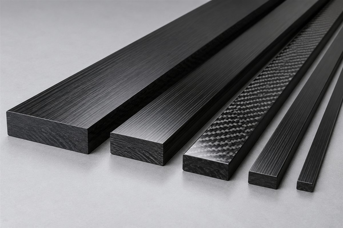
The visible weave is not the full structural definition of a carbon fiber tube. Internal fiber directions determine how the tube responds to bending, torsion, radial load and local connection stresses.
Axial 0° reinforcement
Fibers aligned with the tube axis contribute strongly to longitudinal stiffness. They are important when bending deflection of a long arm is the main design limit.
Off-axis ±45° reinforcement
Off-axis plies help carry in-plane shear and torsion. They become important when the end effector is offset, the arm changes direction rapidly or the connection introduces torque.
Hoop or 90° reinforcement
Hoop reinforcement helps maintain the tube shape and carry circumferential stress around clamps, bonded inserts and local radial loads. A tube optimized only for axial bending can be vulnerable at its interfaces.
Woven surface plies
A woven outer layer can support handling durability and provide a balanced surface appearance, but a 3K plain or twill pattern does not reveal the complete stacking sequence. The distinction between tow size, weave and internal laminate is explained in the 3K carbon fiber and layup guide.
The correct laminate balances the whole load set. Adding axial plies may reduce bending deflection, but a practical automation arm may also need torsional, hoop and damage-tolerance capability.
From Stiffness to Natural Frequency
A structure can be represented conceptually by stiffness and mass. Its natural frequency follows the general relationship:
fₙ ∝ √(k / m)
where k represents structural stiffness and m represents participating mass. Increasing stiffness tends to raise natural frequency, while increasing mass tends to lower it. The distribution of mass also matters: mass near the free end generally has a greater effect on a cantilever-like arm than the same mass close to the support.
This relationship does not provide a complete robot frequency by itself. A pick-and-place assembly has multiple modes, and its joints, brackets, payload and machine frame participate in them. The mode that controls tool-point motion may be a bending mode, a torsional mode or a coupled motion.
Problems can arise when the acceleration profile, repeated cycle rate, motor disturbance or another machine input excites a structural mode. The result can be increased vibration amplitude even when the tube is strong enough for the load.
What Controls Robot Arm Settling Time?
Settling time begins when commanded motion stops and ends when the measured tool position remains inside the required error band. It depends on more than the tube material.
Relevant factors include:
- Natural frequencies and mode shapes of the complete assembly.
- Structural damping in the laminate, adhesive layers and interfaces.
- Backlash or compliance in bearings, drives and joints.
- Payload mass and center of gravity.
- Acceleration, jerk and deceleration settings.
- The width of the permitted position band.
- Sensor location and controller behavior.
Carbon fiber should not be described as automatically eliminating vibration. Laminate, resin, geometry and boundary conditions all affect the dynamic response. A lighter and stiffer member can improve the system, but the benefit must be measured at the end effector under the intended motion cycle.
Joint Compliance Can Dominate a Stiff Tube

An analysis of the tube alone can underestimate tool-point movement. Rotation at the support or end fitting is multiplied by the arm length, so a small angular change can create visible displacement at the tool.
Potential compliance sources include:
- A bonded metal insert and its adhesive overlap.
- Clamp deformation or uneven clamp pressure.
- Clearance in bolted interfaces.
- Bearing and gearbox compliance.
- A thin end-effector mounting plate.
- Local tube-wall deformation at the connection.
Model the connection as part of the load path. Where a threaded metal interface is required, the insert, adhesive, tube wall and transition region should be treated as one structural joint. The custom carbon fiber tube assemblies page shows the relevant interface context for bonded inserts, sleeves and finished tube assemblies. Threads are normally provided by a suitable metal fitting rather than cut directly into a thin composite wall.
A Practical Selection Workflow
- Define the tool-point requirement. Specify allowable displacement, payload, reach, orientation, motion profile and settling band.
- Build the complete mass model. Include the workpiece, gripper, adapters, sensors, valves, cables and fasteners, with mass and center-of-gravity location.
- Define the load cases. Include gravity in relevant orientations, maximum acceleration, braking, torsion from offset loads and required emergency conditions.
- Screen section geometry. Compare bending-axis second moment of area and mass for feasible round, square or rectangular sections.
- Select a laminate concept. Allocate fiber directions for longitudinal bending, torsion, hoop stability and local joint loads.
- Include connection stiffness. Estimate or measure compliance at supports, inserts and the end-effector plate.
- Evaluate dynamic separation. Use modal analysis or test data to compare structural frequencies with motion inputs.
- Prototype and measure. Test the complete assembly with representative payload and motion, then update the model from measured results.
Hypothetical Carbon Fiber Tube Deflection Calculation
Consider an ideal horizontal cantilever used only for first-pass screening. Assume a tube length of 0.80 m, outside diameter 40 mm, inside diameter 34 mm, transverse end load 30 N and effective bending modulus 70 GPa. These are hypothetical teaching inputs, not a Carbosources tube rating.
For the circular section, I = π(D⁴ − d⁴) / 64 = 6.01 × 10⁻⁸ m⁴.
Using δ = FL³ / 3EI, the idealized free-end deflection is approximately 0.00122 m, or 1.22 mm. If the unsupported length increases by 20% to 0.96 m while all other terms remain unchanged, the calculated deflection rises by 1.2³ to approximately 2.10 mm. This comparison shows why reducing span can be more effective than making a small wall-thickness change.
This result excludes tube self-weight, joint rotation, payload offset, laminate coupling, dynamic acceleration and imperfect boundary conditions. If the measured tool-point movement is larger than the beam calculation, measure rotation across the root joint and end fitting before changing the tube. Final selection requires laminate-specific stiffness data and assembly-level testing.
Testing the Assembly
Static deflection test
Apply known loads at controlled positions and measure displacement at the tool point. Test both bending directions if the section or laminate is directional. Record support conditions and temperature.
Joint-rotation measurement
Place measurement points across the connection so tube curvature can be separated from fitting or clamp movement. This prevents a flexible joint from being misdiagnosed as an inadequate tube.
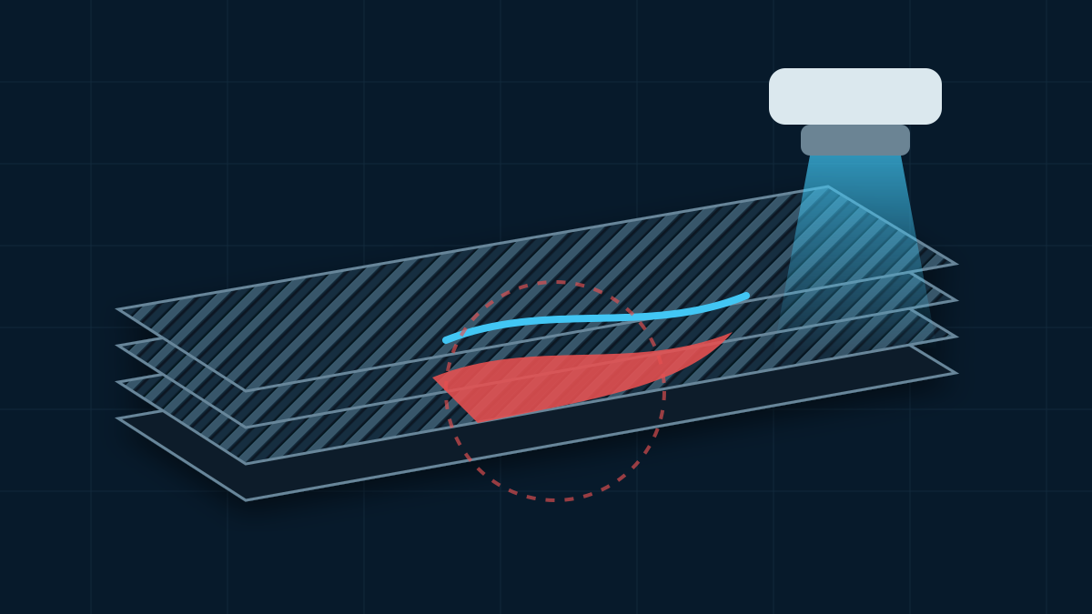
Impact or modal test
An instrumented impact and accelerometer can identify response peaks and mode shapes. The sensor location should reflect the motion of interest at the tool point.
Motion-cycle test
Run the intended acceleration and deceleration profile with representative payload. Measure peak displacement and the time required to enter the allowed position band.
Repeatability and durability test
Repeat measurements after a representative number of cycles and after relevant environmental conditioning. Inspect joints, tube ends and drilled or clamped regions for changes.
Troubleshooting Deflection and Vibration
| Observed behavior | Possible contributors | Useful next check |
|---|---|---|
| Large steady tool offset | Insufficient EI, long span, heavy or offset payload | Static load test and section calculation |
| Tool moves when load reverses | Joint compliance, backlash or clamp slip | Measure rotation across each interface |
| Oscillation after every stop | Structural mode excited by motion profile | Record acceleration and estimate dominant frequency |
| Vibration only at certain speeds | Resonance with a repeated input | Speed sweep or modal test |
| Excess twist but acceptable vertical deflection | Low torsional stiffness or offset load | Torque test and laminate review |
| Position changes after many cycles | Joint degradation, loosening or local laminate damage | Inspection plus before-and-after stiffness test |
| Calculation is much stiffer than the test | Wrong boundary assumption, generic modulus or missing joint compliance | Update the model with measured support and laminate behavior |
Information to Put on the Tube and Assembly Drawing
For a repeatable design, the drawing and process specification should define more than nominal tube size.
Include:
- Outside dimensions, wall construction and length.
- Relevant diameter, straightness, squareness and cut-length tolerances.
- Structural laminate requirements or approved performance criteria.
- Surface finish and cosmetic requirements where they affect sensing or handling.
- Bonded, clamped and machined interface geometry.
- End-fitting alignment and datum scheme.
- Payload coordinate system and primary load directions.
- Inspection points for tool-point deflection and connection alignment.
- Required assembly-level static and dynamic validation.
If the internal laminate is proprietary, the specification can define measurable stiffness, mass and interface requirements rather than an unsupported generic material label.
Frequently Asked Questions
How do you calculate carbon fiber tube deflection?
For initial screening, a tube may be modeled as a beam using the appropriate load and support equation. A cantilever with an end load uses δ = FL³/3EI. The effective laminate bending stiffness, correct section inertia and actual boundary conditions are essential. Validate the assembled arm because joints and payload offsets can add displacement.
Is a larger-diameter carbon fiber tube stiffer?
Usually, increasing the outside dimension increases the section moment of inertia and therefore bending stiffness, assuming the laminate and other variables remain suitable. Packaging, local stability, mass, wall construction and connection design still need review.
Does a thicker wall always reduce robot arm vibration?
A thicker wall changes stiffness and mass at the same time. It may improve local strength or global stiffness, but it is not always the most efficient way to raise natural frequency or shorten settling time. A larger section, shorter span, lighter end effector or stiffer joint may provide a better system-level result.
Which carbon fiber layup is best for a robotic arm?
There is no universal layup. Axial fibers support bending stiffness, ±45° fibers support torsion and shear, and hoop fibers support circumferential stability and local interfaces. The balance should follow the actual load cases and connection details.
Are round or square carbon fiber tubes better for pick-and-place systems?
Round tubes provide an efficient closed section and balanced bending axes, while square or rectangular tubes offer convenient mounting faces and directional packaging options. The better choice depends on bending direction, torque, available space, mounting method and manufacturable laminate.
Why does a pick-and-place arm continue vibrating after it stops?
The deceleration profile may excite a structural mode. Residual motion can also be increased by a heavy end effector, flexible joint, long span, low system stiffness or limited damping. Measure the response at the tool point before deciding which component to change.
Can a tube pass a strength check but still be unsuitable?
Yes. Strength addresses failure, while positioning performance may be controlled by stiffness, natural frequency, joint compliance and settling time. Automation structures are often serviceability-limited before they approach material failure.
The Main Engineering Lesson
Carbon fiber tube deflection and vibration must be evaluated at the system level. Tube diameter, wall thickness and laminate determine only part of the response. Unsupported span, end mass, load offset, joint stiffness, machine frame and motion profile complete the load path.
Begin with the tool-point tolerance and cycle requirement. Use beam equations to compare concepts, include the real interfaces and moving mass, and then test the assembled structure. That process produces a defensible pick-and-place arm design without relying on a generic claim that any carbon fiber tube will automatically be light, stiff and vibration-free.