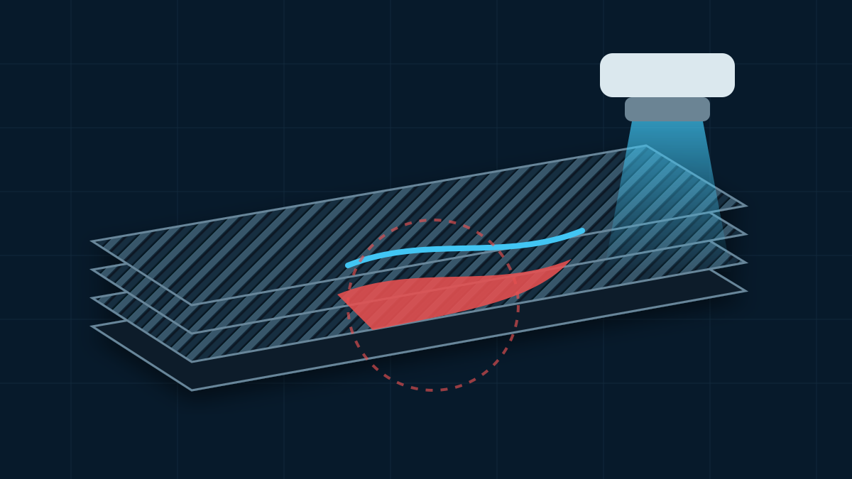
Carbon fiber plate can look intact while damage develops between its internal layers. A shallow dent, a chipped hole edge or a dull response during inspection may indicate a local problem, but none of those observations alone defines the full damage state.
Delamination is separation between adjacent layers of a composite laminate. It is different from a surface coating peeling away, an adhesive joint separating from the plate, or fibers breaking through the thickness. Those damage modes can appear together, which is why a useful diagnosis begins with the load path, manufacturing history and location of the evidence.
This guide explains how carbon fiber delamination can begin during manufacturing, machining, assembly or service; which warning signs justify further inspection; what common inspection methods can and cannot establish; and how designers can reduce risk around edges, holes, fasteners and local load inputs.
What Delamination Is—and What It Is Not
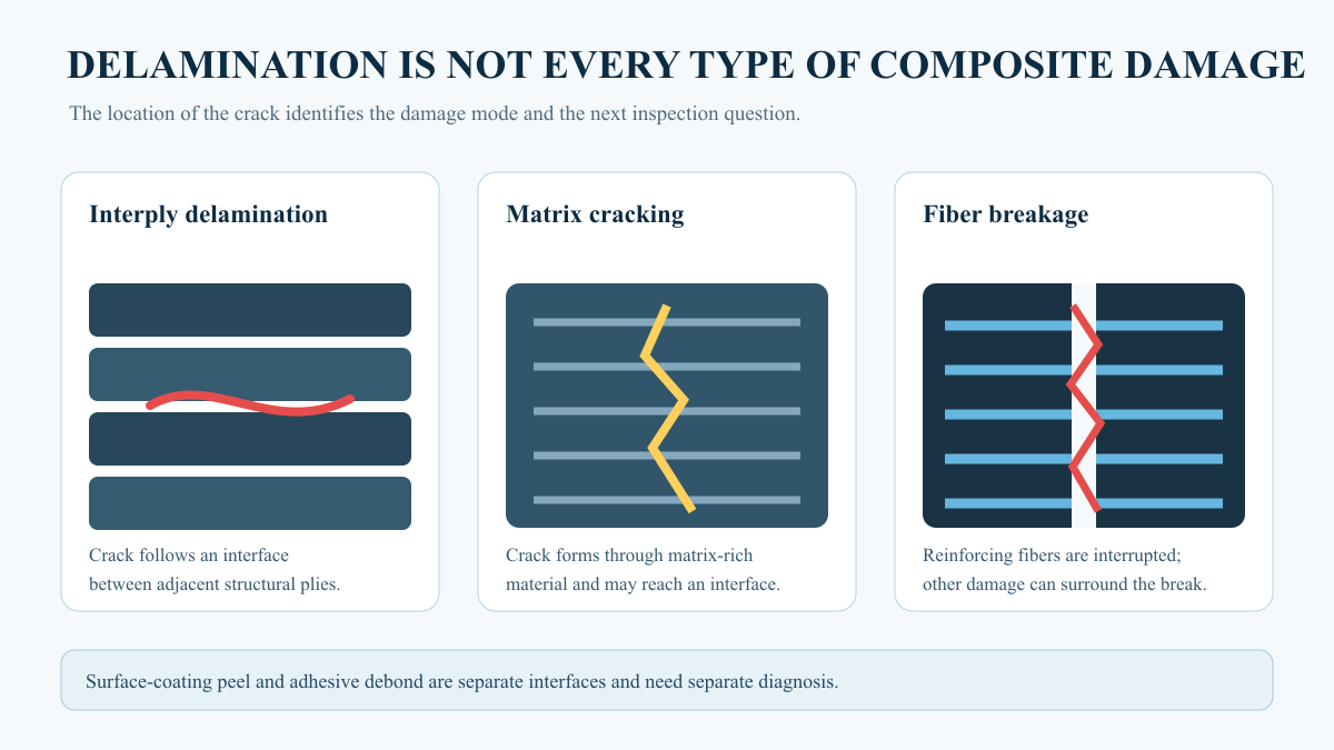
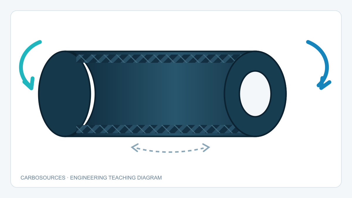
A laminated carbon fiber plate contains multiple reinforced layers joined by a polymer matrix. Most of the in-plane stiffness and strength comes from fibers oriented to carry loads within the plane of the plate. Loads acting between layers rely more heavily on the resin, the fiber–matrix interface and the continuity of the laminate through its thickness.
Delamination forms when a crack grows along an interface between adjacent plies. The separated region no longer transfers interlaminar load in the same way as the intact laminate. Its structural importance depends on its position, size, surrounding layup, loading and whether it grows.
Several visually similar conditions should be distinguished:
| Observation or damage mode | Location | Is it laminate delamination? |
|---|---|---|
| Interply delamination | Between adjacent structural plies | Yes |
| Matrix crack | Within the resin-rich material around fibers | Not by itself, although it can connect to delamination |
| Fiber breakage | Across reinforcing fibers | No, but it may occur in the same impact-damaged zone |
| Fiber pull-out or fraying | Commonly at a machined edge or hole | No, though nearby layers may also be separated |
| Adhesive debond | Between an adhesive and the plate surface | A bond-interface failure rather than internal plate delamination |
| Clear-coat peeling | Between a cosmetic coating and the laminate | Usually a surface-finish problem, not structural delamination |
| Face-sheet/core separation | Between a sandwich-panel skin and its core | A sandwich-interface debond, not interply delamination in a solid plate |
Correct terminology matters because each condition has different causes, inspection needs and design responses.
How an Interlaminar Crack Is Loaded
Engineers often describe interlaminar fracture using three idealized modes.
Mode I: opening
Adjacent layers are pulled apart through the thickness. Peel loading, an unsupported edge or a prying fastener can create an opening component.
Mode II: sliding shear
One layer tends to slide relative to the next in the laminate plane. Bending and in-plane load transfer around discontinuities can produce this condition.
Mode III: tearing shear
The layers experience out-of-plane tearing relative to one another. Real components often combine the three modes rather than producing a pure laboratory case.
These descriptions help explain why a plate with excellent tensile properties along the fibers can still be sensitive to concentrated out-of-plane load. They are not a substitute for laminate analysis or component testing.
Manufacturing Conditions That Can Reduce Interlaminar Quality
Delamination found in service does not automatically prove a manufacturing defect. However, the original laminate condition influences its resistance to later machining, assembly and impact.
Voids and incomplete consolidation
Entrapped air or incomplete compaction can interrupt load transfer locally. The structural significance depends on void size, shape, distribution and location; the presence of a small void does not by itself establish that a component will delaminate.
Resin-starved and resin-rich regions
Insufficient resin can leave incomplete support around fiber bundles. Excess resin can form a locally matrix-dominated region with different stiffness and cracking behavior. Either observation needs to be judged against the material system and acceptance criteria.
Contamination between layers
Dust, release residue, oil or foreign material can reduce bonding at a ply interface. Process controls should prevent contamination rather than rely on visual inspection of a cured surface.
Cure variation
The resin system requires its specified time, temperature and pressure or vacuum history. A cure outside the approved process can affect matrix and interface performance, but appearance alone cannot quantify the resulting properties.
Wrinkles, bridging and abrupt ply termination
Wrinkled fibers, bridging over corners and sudden changes in local thickness can distort the intended load path. They may create resin-rich pockets or interlaminar stress concentrations that become important under bending, compression or impact.
Machining-Induced Delamination

Machining cuts load-carrying fibers and creates free edges. Tool geometry, tool condition, support, clamping and process parameters all affect the resulting damage.
Peel-up at a hole entrance
At the entry face, incompletely cut surface fibers can be lifted by the drill cutting edge or flute. The lifted fibers can pull the upper plies away from the material below them. The resulting damage is commonly described as peel-up delamination.
Push-out at a hole exit
Near the exit face, the remaining uncut laminate becomes progressively thinner. If drilling thrust exceeds the local resistance of those last layers, the tool can push them away before they are cleanly cut. This creates push-out delamination, often accompanied by breakout or uncut fibers.
Worn tools and excessive process heat
Carbon fibers are abrasive. A worn tool can increase cutting forces, heat, fraying and fiber pull-out. Heat can also affect the resin close to the cut. A stable process therefore needs a tool-life criterion rather than waiting for a visibly unacceptable hole.
Unsupported edges and poor clamping
Movement during cutting or inadequate support at the tool exit can increase local bending. Clamping should restrain the workpiece without crushing it or contaminating a surface that will later be bonded.
Edge milling and pocketing
Delamination can occur at an external contour, slot or pocket as well as at a drilled hole. Cutting direction, laminate orientation, tool engagement and the remaining wall all influence edge quality. A smooth-looking top surface does not prove that the lower edge is undamaged.
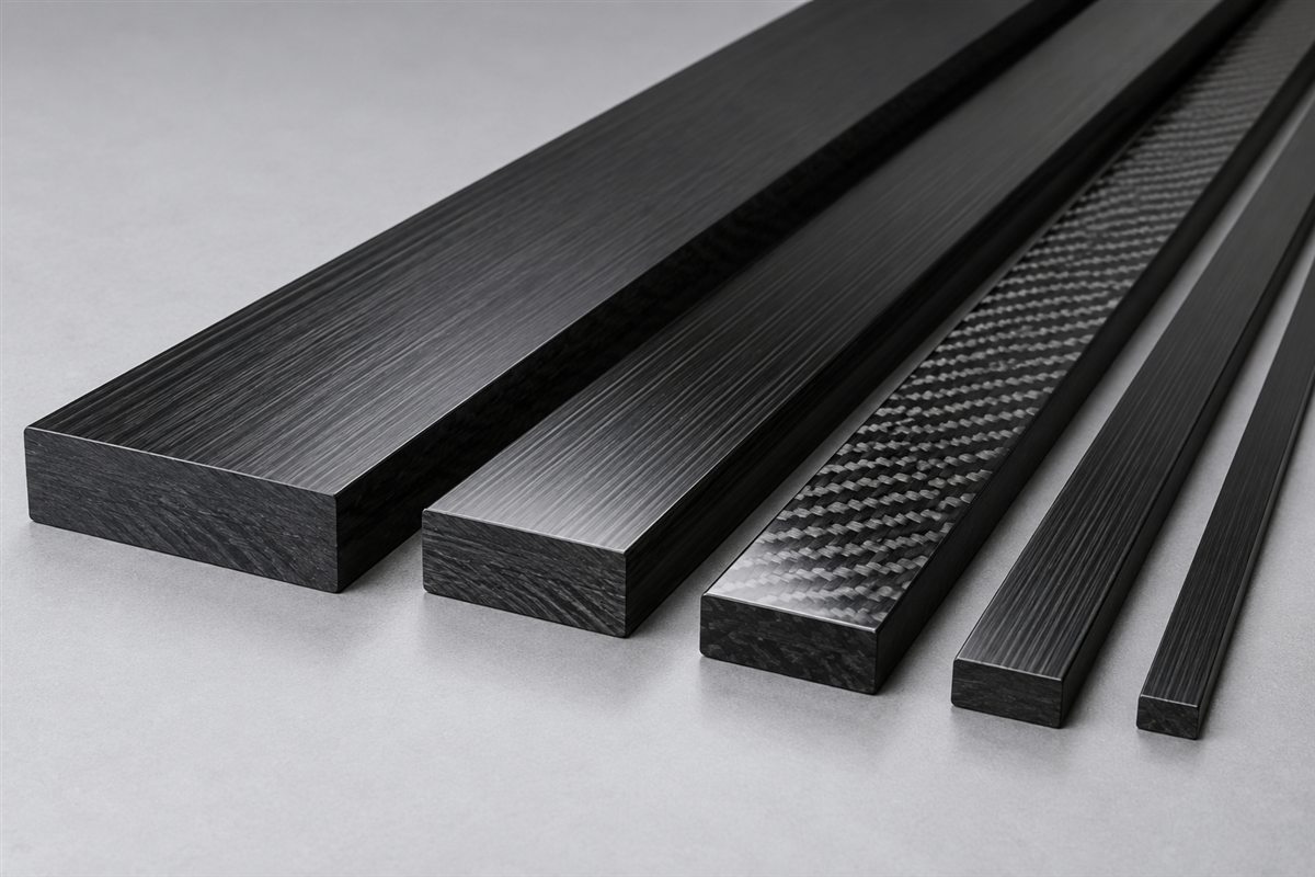
The article on carbon fiber sheet thickness explains how sheet thickness affects part selection. Machining decisions should additionally consider the laminate, feature geometry and required edge quality.
Assembly Loads Around Holes and Fasteners
Drilled holes are not automatically unsafe, but they need a load-transfer design rather than a hole-size callout alone.
Excessive fastener preload
High clamp load applied over a small area can cause local indentation, matrix cracking or crushing. Tightening torque is only an indirect control of clamp force and is influenced by thread and surface conditions.
Small washers and concentrated contact
A small washer or fastener head creates high local pressure. A suitable washer, bushing or load-spreading feature can reduce contact stress, but its geometry must fit the laminate and load path.
Countersunk fasteners
A countersink removes surface plies and introduces an angled bearing surface. If the remaining thickness is inadequate or the fastener is mis-seated, the joint can develop local bending, bearing damage and interlaminar stress.
Insufficient edge distance
Holes close to a free edge may be vulnerable to shear-out, splitting, bearing damage or delamination. There is no universal edge-distance multiplier for every carbon fiber plate: hole diameter, laminate, fastener fit, load direction and thickness all matter.
Interference and press-fit hardware
Forcing an oversized feature into a carbon fiber hole can impose radial load that the laminate was not designed to carry. Press-fit or interference concepts require validated tolerances and local reinforcement rather than assumptions borrowed from metal parts.
Misalignment and prying
Misaligned joint faces can convert intended in-plane load into local bending or peel. Flatness, stack-up and fastener alignment therefore affect laminate damage as well as assembly geometry.
The practical concerns for machined brackets are also relevant to CNC carbon fiber angle brackets and other plate-based connections.
Impact Damage and Barely Visible Evidence
A dropped tool, transport strike or collision with adjacent equipment can produce a combination of matrix cracking, delamination and fiber damage. The visible mark may be smaller than the internal damage region, particularly after a blunt, low-velocity impact.
The term barely visible impact damage, or BVID, describes the inspection challenge rather than a universal damage size. Visibility depends on the surface finish, lighting, dent geometry, laminate and inspection conditions.
ASTM D7136 describes controlled drop-weight impact testing for composite plates. The method emphasizes that impact response depends on specimen geometry, thickness, layup, impactor, energy and boundary conditions. A result from one plate configuration should not be transferred directly to another.
Compression after impact is often important because internal damage can change how a laminate carries compressive load. ASTM D7137 is commonly paired with controlled impact damage to evaluate residual compressive performance. Mentioning these standards does not imply that an untested production plate has a particular damage tolerance.
Fatigue, Bending and Repeated Out-of-Plane Load
Delamination does not always begin with a single impact. Repeated loading can grow damage that starts at a matrix crack, free edge, hole or stiffness transition.
Potential contributors include:
- Reversed or cyclic bending.
- Repeated bearing load at a fastener hole.
- Peel stress at the end of a bonded attachment.
- A concentrated load applied away from the plate mid-plane.
- Vibration combined with clearance or fastener movement.
- A sharp thickness transition or unsupported flange.
- Thermal cycles combined with materials having different expansion behavior.
The important question is not only whether a static proof load was passed. The design should also consider how the load repeats, which interfaces can move and whether damage would be detectable before it becomes critical.
Warning Signs That Justify Further Inspection
No single warning sign proves the size or depth of a delamination. The following observations should instead trigger a defined inspection response.
Visible signs
- A crack following a hole, free edge or impact mark.
- Layers visibly lifting at a machined edge.
- Local whitening or resin cracking around a fastener.
- A dent, bulge or surface distortion after impact.
- Fiber waviness or weave distortion that was not present at acceptance.
- Chipped material or breakout at the lower side of a drilled hole.
Tactile or dimensional signs
- A local soft response under an approved inspection method.
- A raised area or unexpected thickness change.
- Movement between layers at an exposed edge.
- A new loss of flatness near a joint or impact location.
Pressing an unknown damaged area can extend damage. Tactile examination should not be treated as a universal test for a structural part.
Acoustic signs
Tap testing compares the response of a suspect area with a known sound region. A locally duller response can indicate a void, debond or delamination. Results depend on laminate thickness, support, curvature, tool and inspector technique, so tap testing is best treated as a screening method.
Performance changes
- Increased deflection under the same load.
- New vibration or noise.
- Fastener movement or loss of alignment.
- Damage that grows between inspections.
These changes can have causes other than delamination. They justify investigation rather than an immediate diagnosis.
Choosing an Inspection Method
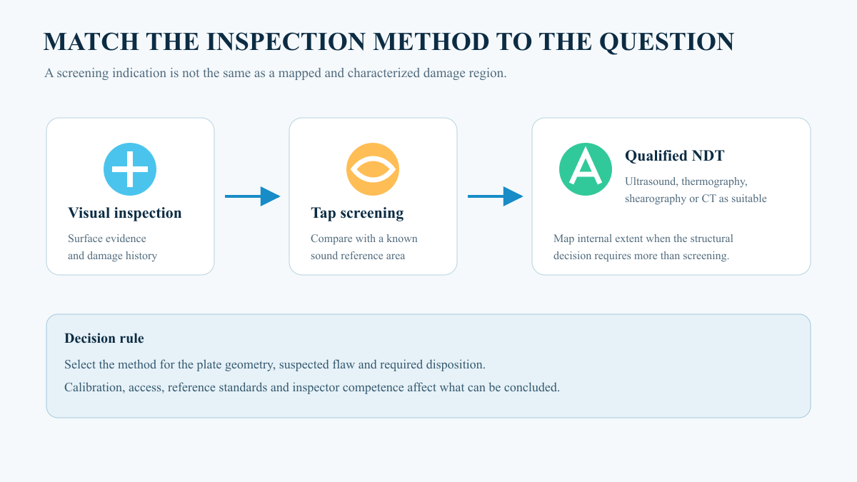
Inspection capability must match the plate geometry, suspected damage and required decision.
| Method | Useful for | Important limitation |
|---|---|---|
| Visual inspection | Surface cracks, lifted edges, impact marks and machining damage | Cannot rule out hidden delamination |
| Tap testing | Rapid screening of accessible areas in suitable structures | Qualitative and dependent on geometry and technique |
| Ultrasonic inspection | Mapping internal interfaces and many delamination-type reflectors | Requires suitable calibration, access and interpretation |
| Infrared thermography | Surveying some near-surface or larger-area anomalies | Depth, heating method and material construction affect sensitivity |
| Shearography | Finding areas with abnormal deformation under controlled excitation | Needs specialized equipment and a suitable load or vacuum stimulus |
| X-ray computed tomography | Detailed internal imaging of suitably sized components | Part size, material thickness, resolution and cost can limit use |
| Stiffness comparison | Detecting a change in overall component response | Does not identify the exact damage type or location by itself |
NASA’s composite nondestructive-evaluation guidance discusses method selection for different flaw types and geometries. FAA composite-repair guidance likewise recognizes visual, tap, ultrasonic, radiographic, shearographic and thermographic techniques. For a structural decision, the procedure, reference standards and inspector competence matter as much as the instrument name.
Design Choices That Reduce Delamination Risk
Keep primary loads in the laminate plane
Where practical, introduce loads as tension, compression or in-plane shear rather than concentrated peel. Brackets and attachments should avoid prying the plate surface away from the laminate.
Spread bearing and clamp loads
Use joint geometry that distributes pressure over an appropriate area. Washers, bushings and bonded load spreaders can help when designed as part of the laminate and not added after damage appears.
Provide a deliberate hole and edge layout
Define hole size, position, edge distance, fastener fit and load direction together. A drawing that gives only nominal plate thickness and hole diameter leaves critical joint behavior unspecified.
Avoid abrupt stiffness transitions
Sudden changes in thickness, reinforcement or attached-part stiffness can concentrate interlaminar stress. A gradual transition or locally supported load path may reduce that concentration.
Match the laminate to the complete load set
Fiber orientation should address the in-plane load, while local details also need through-thickness and damage-tolerance consideration. Surface weave does not define the full stacking sequence; the differences are explained in the guide to plain, twill and unidirectional carbon fiber.
Design the machining process with the part
Hole and contour requirements should be manufacturable with controlled support, tool access and inspection. Critical holes may need a defined process and acceptance plan rather than a generic note to drill after cure.
Protect handling and impact-prone areas
Packaging, fixtures and shop practices should prevent dropped tools, sharp contact and unsupported stacking. Damage prevention begins before the component enters service.
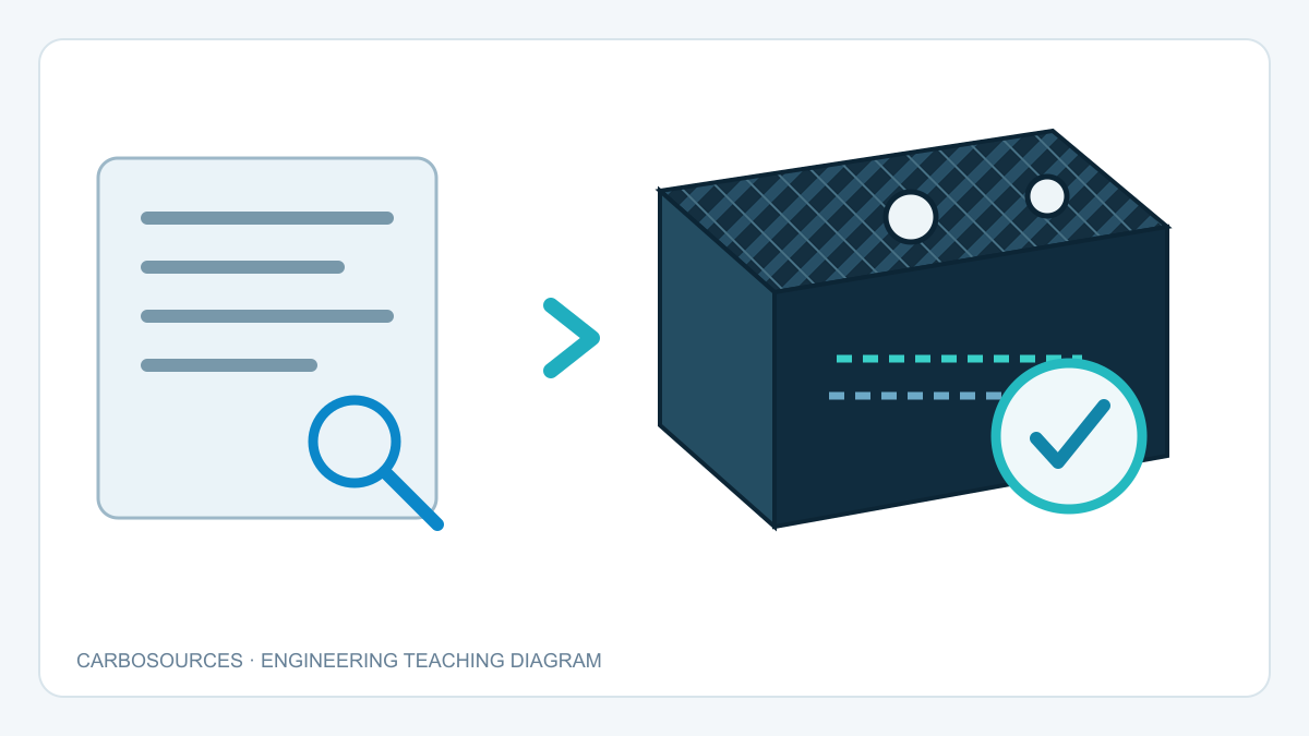
Define inspection and acceptance criteria
Specify which surfaces and features are critical, which indications are unacceptable and which method will verify them. “No delamination” is incomplete if the inspection method and detectable threshold are undefined.
A Hypothetical Mounting-Plate Investigation
Consider a CNC-machined carbon fiber mounting plate with a bolted sensor bracket. After assembly, a fine surface crack is observed near one hole and the bracket shows more rotation under load than expected.
A disciplined investigation would separate evidence from assumptions:
- Record the hole diameter, plate thickness, edge distance, washer size and fastener installation condition.
- Inspect both hole faces to determine whether entry peel-up, exit push-out or edge breakout is visible.
- Check whether the mating bracket is flat and whether misalignment creates a prying load.
- Compare the suspect region with an accepted reference area using an appropriate screening method.
- Use qualified NDT when the structural decision requires knowledge of internal damage extent.
- Review machining records, tool condition and clamping rather than assigning the cause from appearance alone.
- Review assembly preload and service loading to determine whether damage could have grown after machining.
- Decide disposition using the component’s design requirements and an approved engineering process.
This is a hypothetical example. It does not define an allowable crack, a universal repair or the condition of a specific Carbosources product.
Drawing and Process Requirements
A plate drawing and purchase specification can reduce ambiguity by defining:
- Plate dimensions, thickness and relevant flatness requirements.
- Structural laminate or measurable performance requirements.
- Fiber or cosmetic weave orientation where it matters.
- Datum scheme and critical hole-position tolerances.
- Hole type, diameter, countersink and edge-distance requirements.
- Critical load directions and mating-component interfaces.
- Acceptable edge condition after machining.
- Limits for visible breakout, fiber pull-out or lifted plies.
- Whether machined edges require sealing or another controlled finish.
- Inspection method and acceptance criteria for critical regions.
- Traceable process or material records required for the application.
For general product selection, the main carbon fiber sheet page provides the broader context. A structural drawing should then define the particular part rather than relying on a generic material name.
Repair, Rework or Replacement?
The appearance of damage does not determine the correct disposition by itself.
A cosmetic coating defect may need a finish repair without structural laminate work. A machining defect may be removable only if the revised geometry remains within design limits. Internal delamination in a primary load path may require an engineered structural repair or replacement.
Simply injecting resin into a visible opening does not demonstrate restoration of the original load path. A repair decision should consider:
- Damage type, size, depth and location.
- Remaining fibers and surrounding laminate condition.
- Applied static, fatigue and environmental loads.
- Access for preparation and cure.
- Required final contour and tolerances.
- Inspection after repair.
- Evidence that the repaired component meets its required performance.
Safety-critical or regulated components should follow the applicable approved repair data and qualified personnel requirements.
Frequently Asked Questions
What does carbon fiber delamination look like?
Possible signs include lifted layers at an edge, a crack around a hole, a dent after impact, a local bulge or a dull response during tap screening. Delamination can also be hidden, so appearance alone cannot determine the full damage extent.
Can carbon fiber delamination be invisible?
Yes. An impact or local overload can produce internal matrix cracking and interply separation with limited surface evidence. The likelihood and significance depend on the laminate, impact and support conditions.
Does a dull tap sound prove that a plate is delaminated?
No. A dull response can indicate an anomaly, but tap testing is qualitative and affected by geometry, thickness and support. Use a qualified inspection method when a structural decision depends on internal damage extent.
Can drilling cause carbon fiber plate delamination?
Yes. Surface fibers can lift at the entrance, while the remaining plies can be pushed out near the exit. Tool geometry, sharpness, thrust, support and laminate construction all influence the result.
Is peeling clear coat the same as laminate delamination?
Usually not. Clear-coat peeling occurs at the finish layer, while structural delamination occurs between laminate plies. A detailed inspection may be needed when the visible condition is ambiguous or follows an impact.
Can a delaminated carbon fiber plate be repaired?
Some damage can be repaired through an engineered process, while other damage requires replacement. The decision depends on location, size, laminate, load path, repair access and the ability to verify restored performance.
How can delamination risk be reduced around bolt holes?
Use a suitable hole and edge layout, control machining quality, distribute clamp and bearing loads, avoid uncontrolled interference, maintain mating-part alignment and validate the joint under representative loading.
The Main Design Lesson
Carbon fiber delamination is an interlaminar damage mode, not a label for every crack, chipped edge or peeling surface. Its cause may lie in manufacturing, machining, assembly, impact or repeated loading, and the visible evidence may show only part of the damage.
The most reliable prevention strategy is to control the complete load path: select a suitable laminate, avoid concentrated out-of-plane load, design holes and attachments deliberately, machine with a stable process and define inspection before damage occurs. When a suspect indication appears, identify what is known, select an inspection method that can answer the structural question and avoid assigning a repair from appearance alone.