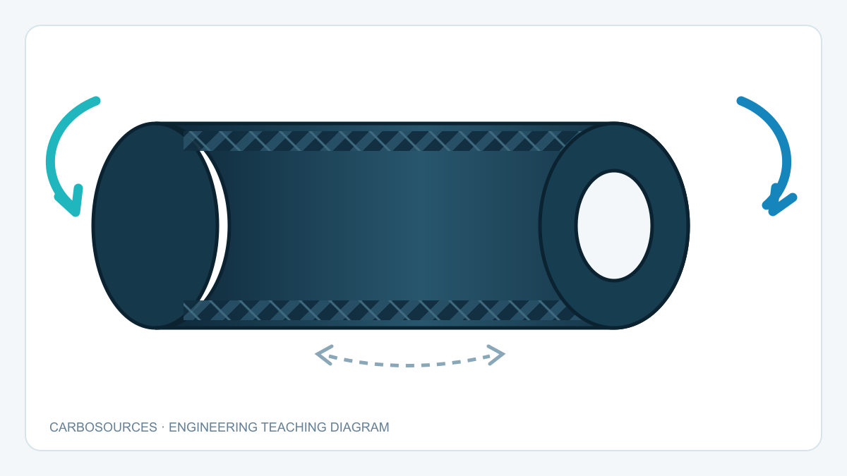
A carbon fiber tube may feel extremely stiff in bending and still rotate more than expected when it transmits torque. The reason is that bending and torsion place different demands on the tube geometry and laminate. Axial fibers that efficiently resist bending do not automatically provide the shear response needed to control twist.
Carbon fiber tube torsional stiffness depends on the tube length and cross-section, but also on fiber orientation, stacking sequence, resin system, manufacturing quality and end connections. Two tubes with the same outside diameter and wall thickness can therefore produce different torque–rotation curves.
This guide explains the geometric relationship between torque and twist, why diameter has a strong influence, how 0°, ±45° and 90° plies contribute, when joints dominate system rotation and how a useful torsion test should be reported. The equations provide engineering intuition; product-specific design values still require controlled material data, laminate analysis and representative testing.
What Torsional Stiffness Means
Torque is a moment acting about the tube axis. It tends to rotate one cross-section relative to another. The resulting angular change is the angle of twist.
Several terms should be separated:
- Torque, T: the applied twisting moment, commonly expressed in N·m.
- Angle of twist, θ: the relative angular rotation between two defined sections.
- Twist per unit length, θ/L: angular deformation normalized by the active gauge length.
- Torsional rigidity: a section-and-material measure commonly represented by GJ for an isotropic tube or by an effective equivalent for a laminate.
- Torsional stiffness: torque divided by angular rotation for a defined assembly and length.
- Torsional strength: the torque associated with a defined damage or failure criterion.
Stiffness answers “how far will it rotate?” Strength answers “what damage limit will it reach?” A tube can meet a strength requirement but allow too much angular error for a camera mount, actuator, robotic axis or measuring system.
The Basic Torque–Twist Relationship
For a uniform, linearly elastic, isotropic circular tube under ideal torsion, the familiar relationship is:
θ = TL / GJ
where T is torque, L is the active length, G is shear modulus and J is the polar second moment of area. For a hollow circular section:
J = π(Dₒ⁴ − Dᵢ⁴) / 32
where Dₒ and Dᵢ are outside and inside diameter.
This equation is useful for geometric intuition, but a laminated carbon fiber tube is not an isotropic metal. Its shear response depends on the properties and orientation of every ply. A single generic carbon-fiber shear modulus should not be inserted without showing how it represents the actual laminate and process.
In preliminary comparisons, engineers may use an effective torsional rigidity obtained from laminate analysis or measured torque–twist data. For a finished system, the end fittings, bondlines, clamps and test fixture may add rotation that is not part of the tube wall itself.
Why Diameter Has a Strong Effect

Material resists torsion more efficiently when it lies farther from the tube axis. This is why increasing tube diameter can improve torsional rigidity much faster than its linear change suggests.
For a thin-walled circular tube with mean radius r and wall thickness t, the geometric torsion parameter is approximately proportional to:
J ≈ 2πr³t
Under this approximation, if laminate, length and wall thickness remain unchanged, increasing mean radius by 20% changes the geometric term by approximately:
1.2³ = 1.728
That is about a 73% increase in the geometric torsion parameter. This is a teaching comparison, not a product rating. Changing diameter can also alter mass, local stability, fittings, manufacturing route and available installation space.
The comparison basis must always be stated. “Larger diameter is stiffer” may refer to constant wall thickness, constant inside diameter, constant material area or constant mass. Each constraint produces a different design tradeoff.
How Wall Thickness Affects Twist
At a fixed mean diameter, adding wall thickness generally increases the section’s torsional rigidity. For a sufficiently thin wall, the geometric contribution is approximately proportional to thickness. As the wall becomes less thin relative to diameter, the full hollow-section expression provides better geometric representation.
For carbon fiber tubes, adding thickness also means adding plies. Their orientation matters. Four extra 0° plies and four extra ±45° plies add the same nominal thickness but do not contribute equally to torsional shear response.
Wall thickness also affects:
- local buckling resistance;
- clamp and fastener contact behavior;
- machining allowance;
- insert and bondline geometry;
- damage tolerance;
- mass and outside envelope.
The guide to carbon fiber tube diameter and wall thickness discusses bending and sizing considerations. For torsion, the laminate architecture must be added to the geometry discussion.
How Length Changes Angular Rotation
For a uniform tube operating in its linear range, angle of twist is proportional to active length. Doubling the length while holding torque, geometry and effective torsional rigidity constant approximately doubles rotation.
The important dimension is the actual torque-transfer length, not necessarily the cut length. A bonded insert may transfer load gradually into the tube wall. A clamp may restrain a region rather than a single cross-section. The distance between effective load-transfer locations should therefore be defined when comparing test results.
Long tubes can also make small fixture or joint rotations easier to detect but harder to separate from tube deformation. Short specimens may be dominated by end effects. A meaningful report identifies the gauge length and where rotation was measured.
Why ±45° Plies Matter in Torsion

Torque applied to a circular tube produces in-plane shear in the wall. Fibers oriented at +45° and −45° relative to the tube axis are well placed to convert that shear deformation into tension and compression along the reinforcement directions.
A balanced ±45° pair supports torque in both directions and helps control unwanted coupling. This does not mean every torque tube should contain only ±45° plies. The tube may also need axial stiffness, bending stiffness, hoop stability, impact resistance or a particular connection design.
| Ply direction relative to tube axis | Primary contribution | Torsional role |
|---|---|---|
| 0° | Axial and bending response | Important to overall structure but usually not the most efficient direction for wall shear |
| +45° / −45° | In-plane shear transfer | Commonly the main torsion-oriented reinforcement |
| 90° | Hoop response and section stability | Helps maintain tube shape and supports local or pressure-related requirements |
| Mixed laminate | Balanced multi-axis performance | Trades torsion against bending, axial, stability and damage requirements |
Thin composite torque-shaft research has identified balanced ±45° laminates as an effective configuration when other design requirements permit. The qualification is important: a robotic beam that also carries bending, a pressure tube and a pure torque shaft need different balances.
Why More 0° Fiber Is Not Always Better
The phrase “more longitudinal carbon” is often associated with greater stiffness. That can be correct for axial loading and bending because 0° fibers run along the tube and efficiently resist lengthwise strain.
In torsion, however, the wall is dominated by shear. A laminate heavily biased toward 0° may have excellent bending stiffness yet allow more twist than a laminate with a suitable ±45° contribution. It may also place more of the shear demand into the matrix and off-axis response.
The opposite extreme has its own tradeoff. Replacing too many 0° plies with ±45° plies may reduce axial or bending stiffness needed by the system. The design question is not “Which angle is best?” but “What combination carries all required load cases with acceptable deformation and damage margin?”
The article on plain weave, twill weave and unidirectional carbon fiber explains why visible weave is not the same as internal load-carrying orientation. A woven cosmetic surface cannot by itself reveal the full tube layup.
Balanced, Symmetric and Coupled Layups
Composite laminates can couple one type of load or deformation to another. A tube under torque may also develop axial strain, radial change or bending if its material architecture and geometry produce coupling.
Three terms help organize the design:
- Balanced: positive and negative angle plies are present in matching proportions.
- Symmetric: the stacking sequence mirrors about the laminate mid-plane.
- Coupled: one applied load produces an additional deformation mode, such as torque producing extension or bending producing twist.
Balanced and symmetric construction is commonly used to reduce selected couplings and manufacturing distortion, but the complete tube still needs analysis. Curvature, different radii through the wall, hybrid materials, local reinforcements, ply overlaps and end details can change behavior.
Temperature also matters. An off-axis laminate can develop thermal twist because fiber and matrix expansion differ by direction. If angular alignment must remain stable through a temperature range, the analysis should include the complete laminate and boundary conditions rather than room-temperature mechanical stiffness alone.
Round, Square and Rectangular Tubes in Torsion
A circular closed section offers a continuous wall at constant radius and tends to produce a relatively uniform torsional load path. This makes round tubes attractive for torque transmission and simplifies interpretation of twist.
Square and rectangular tubes are also closed sections, but their flat walls and corners produce a different shear-flow distribution. Corner geometry, fiber continuity and manufacturing method become important. A rectangular tube can be efficient in directional bending while having torsional behavior that cannot be inferred from its strong bending axis.
Open sections behave differently again. A slit tube, channel or partially bonded seam may have much lower torsional rigidity than a comparable closed section because the shear path is interrupted.
When selecting carbon fiber rectangular tubes, consider bending orientation, torsion, attachment surfaces and corner construction together. A direct substitution based only on outside width and height can miss the load-path difference.
End Connections Can Dominate System Twist

The measured rotation of an assembly is rarely produced by the tube wall alone. A useful system model adds the angular deformation of each load-transfer element:
θsystem = θtube + θbond + θinsert + θjoint + θfixture
Potential sources include:
- adhesive shear deformation;
- insert deformation or slip;
- clearance in bolts, pins or splines;
- local tube-wall deformation under a clamp;
- insufficient bonded overlap;
- flexible end plates;
- test-fixture compliance.
A very stiff tube connected through a short, flexible bond can still produce poor angular accuracy. Increasing tube diameter or adding ±45° plies will not correct rotation that occurs primarily in the joint.
The guide to bonded inserts in carbon fiber tubes explains load transfer, overlap length and common insert failure modes. Joint stiffness should be measured or modeled with the same care as tube stiffness when the system has a tight rotation limit.
Common Failure Modes Under Torque
Torsional failure is not limited to a clean spiral break. Damage can start before obvious collapse and may progressively change stiffness.
Matrix and off-axis cracking
Repeated or excessive shear can initiate cracks in matrix-dominated regions or transverse to selected plies. Surface appearance may not show the full internal extent.
Delamination
Ply cracks, local defects and abrupt changes in stiffness can drive separation between layers. Delamination can reduce effective load transfer and may grow under cyclic torque. The carbon fiber delamination guide describes inspection limits and why visible condition alone is not a complete diagnosis.
Fiber failure
The +45° family is loaded differently from the −45° family under a given torque direction. Depending on material and sequence, one family may be dominated by tension and the other by compression. Fiber fracture, microbuckling or kink-related damage may occur when local strain limits are exceeded.
Local buckling and ovalization
Thin tube walls can become locally unstable. Clamps, cutouts, insert ends and unsupported regions can introduce nonuniform stress that lowers the usable torque level.
Joint failure
Bondline shear failure, peel at the overlap end, insert pull-out, tube splitting and clamp slip can all limit assembly torque before the main tube wall reaches its own material limit.
Static and Cyclic Torsion Are Different Questions
A single increasing torque test can establish an initial torque–rotation curve and identify a selected proof or failure condition. It does not automatically describe long-term response under repeated reversing torque.
Cyclic torsion may produce:
- progressive matrix cracking;
- delamination growth;
- joint fretting or slip;
- hysteresis between loading and unloading;
- residual rotation;
- gradual stiffness change.
The duty cycle should specify torque range, mean torque, reversals, cycle count, temperature and inspection intervals. A system that repeatedly changes direction can challenge bondlines and backlash differently from a shaft loaded mainly in one direction.
How to Test Carbon Fiber Tube Torsional Stiffness
A useful test controls both the applied torque and the measurement of twist. The report should include enough information for another engineer to understand what the result represents.
Record at least:
- specimen outside and inside diameter or measured wall thickness;
- active gauge length;
- material and laminate identification available for the specimen;
- manufacturing route;
- end-fitting and grip design;
- torque range and loading rate;
- rotation measurement locations;
- loading direction and number of cycles;
- environmental conditioning and test temperature;
- whether fixture compliance was measured or removed;
- observed damage and the criterion used to stop the test.
Plot torque against rotation. If the response is linear over the working range, its slope gives assembly torsional stiffness for the defined length. Also inspect unloading behavior. Hysteresis or residual angle can indicate fixture motion, joint slip, viscoelastic response or damage.
For tube-only characterization, measure rotation between two marks or sensors on the tube away from the grips. For assembly validation, include the actual inserts, adhesive and hardware because their compliance is part of the application.
Worked Example: Three Ways to Reduce Twist
Consider a hypothetical carbon fiber torque tube for an automated rotary axis. The current design meets strength requirements but rotates more than the angular error budget allows. Three changes are considered.
| Concept | Change | Expected torsional effect | Main tradeoff |
|---|---|---|---|
| A | Add 0° plies at the same diameter | Small or moderate improvement depending on the original laminate | Adds mass but may target bending more than shear |
| B | Replace selected plies with balanced ±45° reinforcement | Improves wall shear response | Can reduce axial or bending contribution if total thickness stays fixed |
| C | Increase diameter and rebalance the laminate | Strong geometric and laminate improvement | Requires more installation space and new end fittings |
The correct choice depends on the complete load set. If rotation occurs mainly in the bonded insert, none of the three tube-wall changes may solve the problem. The first step is to separate tube twist from joint and fixture rotation.
For concept comparison, an engineer may normalize measured stiffness rather than publish unsupported absolute values. For example, the baseline assembly can be 1.00, with revised concepts compared under the same torque, length, boundary condition and measurement method.
Torsional Stiffness Design Checklist
Before specifying or comparing a torque-carrying carbon fiber tube, answer the following questions.
| Design area | Question |
|---|---|
| Load | What continuous, peak and reversing torque must be carried? |
| Rotation | What is the maximum permitted angular change at the functional interface? |
| Length | What is the effective distance between torque-transfer regions? |
| Geometry | Are outside diameter, inside diameter, wall thickness and mass constrained? |
| Combined loads | What bending, axial, pressure, impact or clamp loads act at the same time? |
| Layup | Is the ±45° content appropriate for wall shear while retaining other required directions? |
| Coupling | Could the laminate produce extension–twist, bend–twist or thermal twist? |
| Section | Is the tube circular, rectangular, open, slotted or locally interrupted? |
| Joints | How much rotation occurs in bondlines, inserts, clamps and hardware? |
| Stability | Are local buckling, ovalization and clamp crushing relevant? |
| Durability | Is the requirement static, repeated, reversing or temperature-dependent? |
| Test | Are torque, gauge length, rotation points, fixtures and conditioning reported? |
| Acceptance | Is the limit based on stiffness, residual rotation, damage onset or ultimate failure? |
Carbon fiber tube torsional stiffness is a system property built from geometry, laminate and connections. Diameter can provide a strong geometric advantage, while balanced ±45° reinforcement commonly carries the wall shear generated by torque. Length determines how that deformation accumulates, and joints may contribute more rotation than the tube itself. A useful design therefore specifies the allowed twist and load case first, then evaluates the complete torque path with controlled analysis and representative testing.