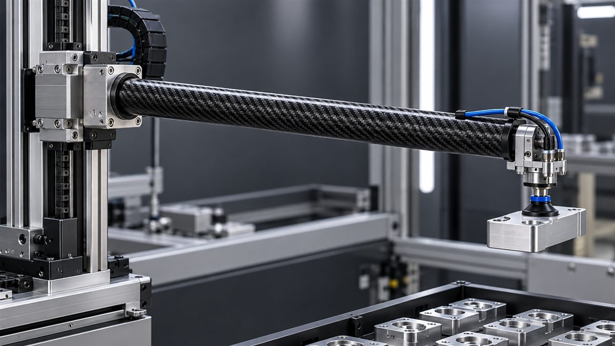
A bonded insert is often the smallest component in a carbon fiber tube assembly, but it can control the capacity, alignment and durability of the entire structure. The thread or clevis on the metal fitting may look like the critical feature. In practice, the joint must transfer load from that hardware, through the insert and adhesive, into a directional composite tube wall.
That load path is why carbon fiber tube inserts cannot be selected from thread size alone. A larger thread does not automatically provide a stronger joint, and a longer insert does not increase capacity in direct proportion to its length. Tube diameter, wall thickness, laminate orientation, insert stiffness, bond-line thickness, surface preparation and service environment all change the result.
This guide explains how bonded inserts carry axial, torsional and bending loads; what controls adhesive overlap length; how common failure modes differ; and what engineers should put on the drawing before a joint is manufactured or tested.
Start with the Complete Load Path
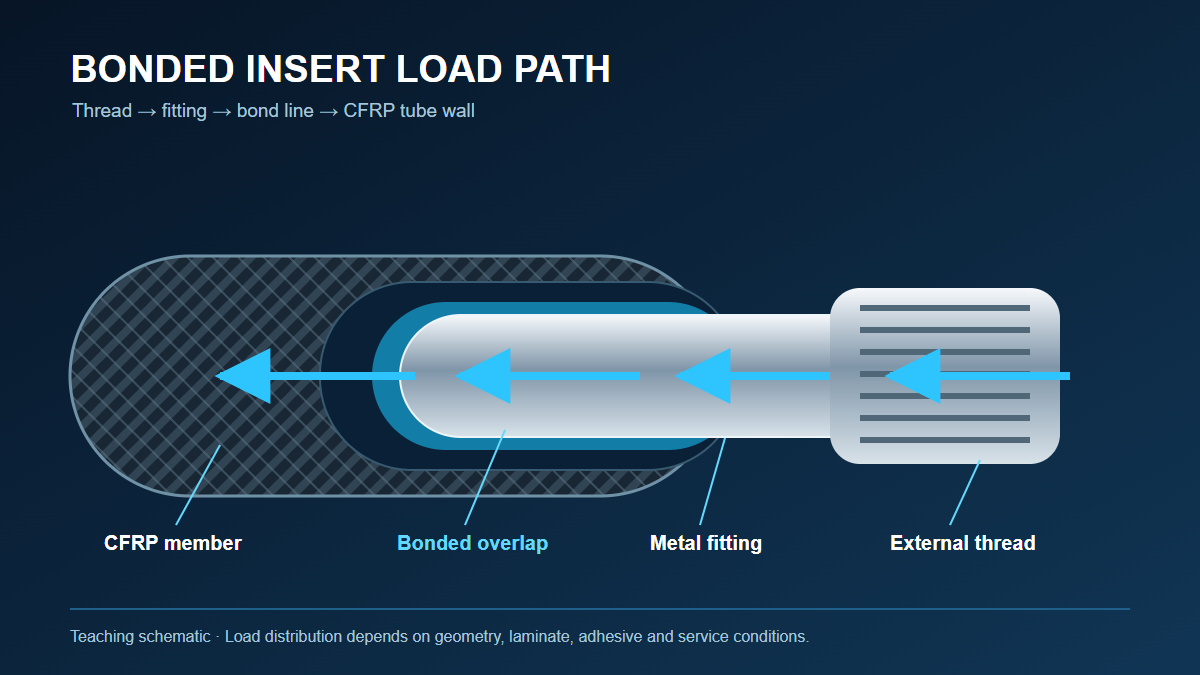
A threaded connection concentrates load in a relatively small metal feature. The bonded overlap must spread that load around the tube circumference and along the tube axis before the composite wall can carry it efficiently.
The main elements are:
- External interface: thread, clevis, stud, flange or bracket that receives the applied load.
- Metal insert or end fitting: carries local thread, bearing, bending and installation loads.
- Bond line: transfers force between the insert and the composite through shear, with local peel or normal stresses near discontinuities.
- CFRP tube wall: carries the load through its laminate, with different fiber directions contributing to axial, hoop and shear behavior.
- Transition region: the area around the end of the insert where stiffness changes and local stresses can rise.
If any one of these elements is weaker than expected, improving the other elements may not increase assembly capacity. A high-strength adhesive cannot compensate for a contaminated surface. A long overlap cannot prevent a thin tube from splitting under radial stress. A thick metal fitting may survive the thread load while creating a sharper stiffness transition at the end of the bonded region.
How Different Loads Enter a Bonded Insert
Axial tension
An axial tensile load attempts to pull the insert out of the tube. The insert transfers this force into the adhesive, and the adhesive transfers it into the tube wall over the bonded overlap.
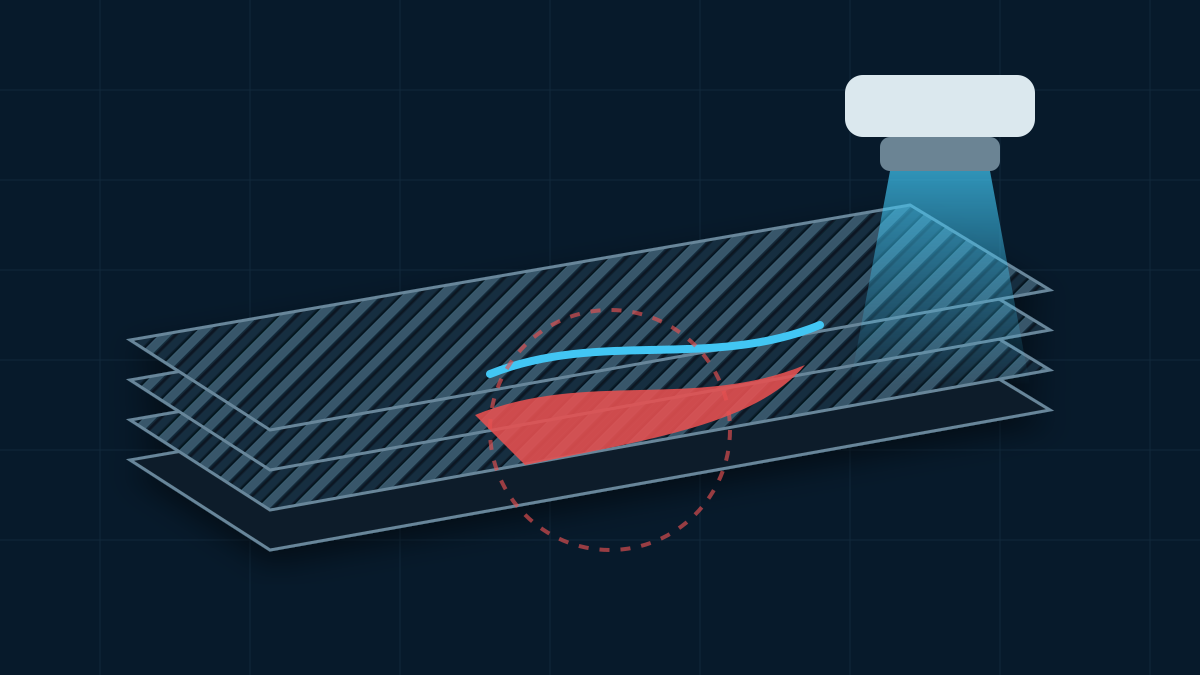
A simple average shear calculation divides axial force by nominal bond area. That can be useful for an initial comparison, but it does not describe the real stress distribution. Shear stress is commonly higher near the ends of the overlap, and local peel stress can develop where the adherends change stiffness or the load is eccentric.
This means the joint can fail at an overlap edge even when the calculated average shear stress appears modest.
Axial compression
Compression can travel through the adhesive, through an intentional insert shoulder, through tube-end contact, or through a combination of these paths. The drawing should make the intended path clear.
Uncontrolled end contact can create local crushing or an assembly-length error. If a shoulder is designed to carry compression, its face, perpendicularity and contact condition become structural features rather than simple machining details.
Torsion
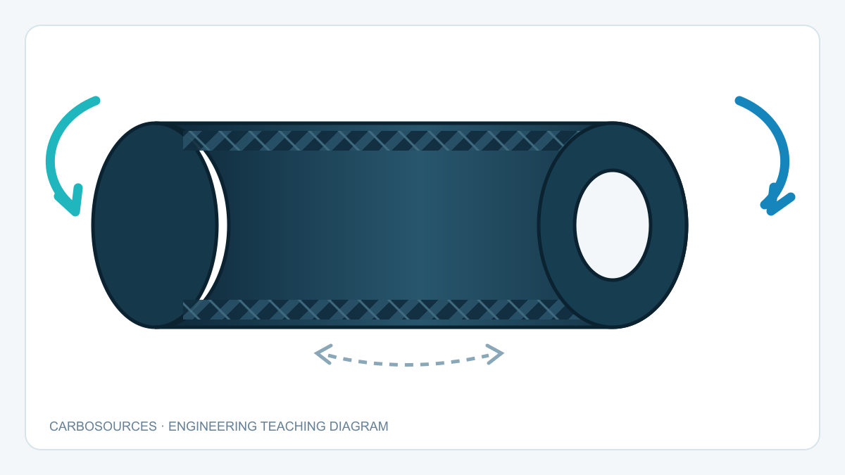
Torque is transferred through circumferential shear in the bond line. Bond diameter, overlap length, adhesive behavior and insert anti-rotation geometry all matter. The tube laminate also needs sufficient off-axis reinforcement. A tube dominated by axial 0° fibers may have excellent longitudinal stiffness but limited ability to carry torque into the main span.
Bending and offset loading
An external rod end, bracket or clevis can place the load line away from the tube centerline. The resulting moment can increase peel stress at one side of the overlap and compression at the other. A centered axial pull test may not reproduce this condition.
Combined and cyclic loading
Many real joints see tension, compression, torsion and bending in sequence rather than one isolated load. Robotic linkages reverse direction. Motorsport members experience vibration and repeated adjustment. Actuator rods may see axial load combined with a small alignment error. The qualification plan should represent the combined load path that matters in service.
Common Insert and End-Fitting Configurations
Internal spigot insert
An internal insert fits into the tube bore. It keeps the outside profile clean and is widely used for threaded ends, clevises and rod-end connections.
Its performance depends on the actual tube inside diameter, not only the nominal value. A bore that varies along the overlap can create an uneven bond line, scrape adhesive from the insert during assembly or tilt the fitting away from the tube axis.
External sleeve or ferrule
An external fitting bonds over the tube outside diameter. This can simplify adhesive application and provide local hoop support, but it increases the external envelope and moves the stiffness transition to the sleeve edge.
Surface finish and outside-diameter tolerance become important. The design also needs to address environmental sealing and direct contact between CFRP and the selected metal.
Internal and external reinforcement
Some joints support the tube from both sides or use a local overwrap around an internal fitting. This can produce a more controlled load path, but it adds manufacturing steps, mass and additional interfaces. It should be treated as a designed joint rather than an automatic upgrade.
Bonded insert with mechanical retention
Pins, holes, keys, grooves or shoulders can supplement adhesive bonding. These features can prevent rotation or provide a secondary load path, but they also introduce bearing stress, fiber interruption and new stress concentrations.
A hybrid joint requires analysis of how the adhesive and mechanical feature share load. It should not be assumed that both systems reach their full standalone capacity at the same time.
| Configuration | Main advantage | Main design concern |
|---|---|---|
| Internal insert | Compact, clean external surface | Tube-ID tolerance and adhesive coverage |
| External sleeve | Accessible bond surface and local hoop support | Larger envelope and sleeve-edge stresses |
| Internal plus external support | More controlled local support | Added mass, parts and interfaces |
| Hybrid adhesive-mechanical joint | Secondary retention or anti-rotation | Drilled fibers, bearing load and load sharing |
What Determines Adhesive Overlap Length?
There is no universal overlap-length-to-diameter ratio for every bonded insert carbon fiber tube joint. A valid overlap depends on geometry, materials, loading and the acceptable failure mode.
Important inputs include:
- axial tension and compression;
- applied torque and bending moment;
- tube inside or outside diameter;
- effective bonded circumference;
- CFRP wall thickness and layup;
- insert material, wall thickness and stiffness;
- adhesive shear, peel and temperature behavior;
- bond-line thickness;
- static, cyclic or impact loading;
- moisture, chemicals and service temperature;
- available joint length and mass.
Why longer is not linearly stronger

The bond line does not normally carry uniform shear from one end to the other. Load builds and transfers through the overlap, with elevated stresses often appearing near its edges. When a very short overlap is lengthened, the additional area can provide a substantial benefit. As the overlap becomes longer, the added central area may carry less incremental load than an average-stress calculation suggests.
At that point, the controlling failure may move elsewhere: into the composite wall, the insert, the thread or the transition region. This is why multiplying nominal adhesive shear strength by bond area can overpredict what the complete assembly will carry.
Insert stiffness changes the stress distribution
Steel, titanium and aluminum fittings do not deform in the same way, and none necessarily matches the local axial, radial or torsional stiffness of a CFRP tube. A stiff fitting can concentrate load near the overlap edge. A more compliant transition may reduce one stress component while creating another limitation in the fitting.
Design options can include a controlled taper, a gradual wall change, a longer transition, local laminate reinforcement or a different insert material. Each option needs to be checked against the full load case rather than selected from appearance alone.
Tube wall and laminate can become the limit
Increasing overlap may eventually make the adhesive interface stronger than the adjacent composite. The joint can then fail through delamination, resin-dominated shear, fiber tear or tube splitting. That result is not automatically good or bad; it shows that the weakest link has moved and that the tube construction now controls the joint.
Bond-Line Thickness, Fit and Concentricity
An insert that feels tight during dry assembly is not necessarily ready for bonding. Adhesive needs a controlled space, and that space must remain sufficiently uniform around the circumference and along the overlap.
Problems with insufficient clearance
- adhesive can be scraped from the surfaces during insertion;
- high spots in the tube bore can create starved regions;
- trapped air and excess adhesive may have no exit path;
- a press fit can introduce radial stress into a thin tube wall;
- the insert may stop before reaching the required depth.
Problems with excessive clearance
- the bond line can become thick and uneven;
- the fitting can shift or tilt during cure;
- adhesive mass and cure shrinkage increase;
- concentricity and final thread position become harder to control;
- repeatability depends too heavily on the fixture.
The drawing and process should therefore control:
- tube ID or OD over the complete bonded zone;
- insert bonding diameter;
- diametral clearance;
- insertion depth;
- axial position;
- concentricity and angular alignment;
- thread runout;
- the method used to maintain the bond gap.
The carbon fiber tube tolerance guide explains why a functional fit requires more information than a single nominal diameter.
Surface Preparation Is Part of the Joint Design
Surface preparation cannot be treated as a shop-floor detail added after the fitting geometry is released. It affects the interface that must carry the load.
CFRP surface preparation
The inside or outside tube surface may contain release-agent residue, handling contamination, a resin-rich finish or machining dust. Preparation must expose a clean and bondable surface without uncontrolled removal of structural fibers.
A controlled procedure normally defines the permitted abrasion method, cleaning materials, drying, contamination control and maximum time between preparation and bonding. If peel ply is used to create a bond-ready surface, its material and removal procedure still need control.
Metal surface preparation
Aluminum, stainless steel and titanium require different treatment plans. Degreasing alone may not provide durable adhesion. Depending on the approved adhesive system, the process may include abrasion, blasting, chemical treatment, primer or conversion coating.
The prepared fitting should be protected from fingerprints, dust and re-oxidation before adhesive application.
Carbon fiber and aluminum isolation
Carbon fiber is electrically conductive. If exposed carbon and aluminum are electrically connected in the presence of moisture or another electrolyte, galvanic corrosion can attack the aluminum.
Possible controls include a durable barrier layer, suitable coating, sealed interface, insulating layer or a different insert material. Adhesive coverage may contribute to isolation, but the design should not assume that an uncontrolled bond line will remain a perfect environmental barrier throughout service.
Adhesive Application and Cure Control
Even a suitable structural adhesive can produce an unreliable joint if mixing, application or cure is inconsistent.
The process should address:
- adhesive identification and batch;
- storage and conditioning;
- mix ratio and mixing method;
- working time;
- application to one or both surfaces;
- prevention of trapped air;
- control of bond-line thickness;
- insert position during cure;
- cure temperature and time;
- post-cure where required;
- inspection of squeeze-out and witness features.
Long internal overlaps can be difficult to wet completely. Simply coating the end of an insert and pushing it into the tube may move adhesive toward one end and leave voids elsewhere. Depending on the geometry, the process may need controlled metering, injection, venting or assembly witness features.
Fixtures should locate the thread or fitting from functional datums. Holding only the tube OD does not guarantee that the thread axis will remain concentric if the tube wall or bore varies.
Failure Modes of Bonded Carbon Fiber Tube Inserts

The phrase “insert pull-out failure” describes the final event, not necessarily the root cause. The surfaces left after testing provide important evidence.
Adhesive failure at the CFRP interface
The adhesive separates from the composite surface, leaving much of the CFRP relatively clean. Possible causes include contamination, release residue, inadequate surface preparation, a weak resin-rich layer or environmental degradation.
Adhesive failure at the metal interface
The adhesive separates from the fitting. Metal oxidation, poor cleaning, incompatible primer, delayed bonding after preparation or an unsuitable surface treatment may contribute.
Cohesive failure in the adhesive
The crack travels through the adhesive, leaving adhesive on both adherends. This shows that the interfaces resisted the crack at that location, but it does not prove that the assembly meets its required load or durability.
CFRP delamination or fiber tear
The bond removes resin, plies or fibers from the tube. The interface may be stronger than the adjacent composite, or the fitting edge may be concentrating interlaminar stress. The laminate and transition geometry then require review.
Tube splitting or hoop cracking
Longitudinal cracks near the tube end can result from radial installation pressure, an expanding fitting, inadequate hoop reinforcement, a sharp insert feature or local bearing load.
Insert yielding or thread failure
The adhesive joint may remain intact while the metal fitting bends, the threaded section strips or a shoulder fractures. Thread engagement and fitting wall thickness belong in the same verification plan as the bond.
Fatigue damage at the overlap edge
Small edge cracks or disbonds can grow under repeated axial reversal, vibration or torsion. A static pull-out test may not reveal this risk.
| Evidence after failure | Probable failure region | What to investigate next |
|---|---|---|
| CFRP surface is relatively clean | CFRP-to-adhesive interface | Contamination, release residue and surface preparation |
| Metal surface is relatively clean | Metal-to-adhesive interface | Oxide, cleaning, primer and preparation delay |
| Adhesive remains on both surfaces | Cohesive adhesive failure | Cure, bond thickness, temperature and required load |
| Resin or fibers remain on the fitting | CFRP intralaminar failure | Layup, tube wall and insert-edge stress |
| Tube has longitudinal cracks | Hoop or radial failure | Fit, insertion force, end geometry and hoop plies |
| Insert rotates without pulling out | Torsional load-path failure | Anti-rotation geometry, bond coverage and ±45° reinforcement |
How Tube Layup Changes Joint Behavior
The surface weave does not define the complete tube laminate. Different fiber directions carry different parts of the joint load.
Axial 0° reinforcement
Fibers running along the tube axis provide longitudinal stiffness and carry much of the axial load in the main tube span. They do not by themselves provide strong hoop restraint or an efficient torsional load path.
Off-axis ±45° reinforcement
Off-axis fibers contribute to in-plane shear and torsion. A joint expected to transfer significant torque needs a tube laminate capable of moving that load beyond the insert region.
Hoop or 90° reinforcement
Circumferential reinforcement helps the tube retain shape and resist splitting, local expansion and radial load. It may be especially important where a fitting changes the local radial stiffness.
Woven surface plies
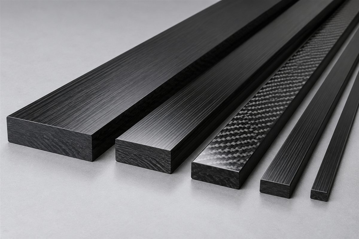
A woven outer ply can support handling, appearance and multidirectional surface behavior, but “3K twill” does not specify the structural laminate below it. The 3K carbon fiber guide explains the difference between tow size, surface weave and internal layup.
Testing a Bonded Insert Assembly
Testing should reproduce the intended load path and record the resulting failure mode.
Dimensional inspection
Before mechanical testing, verify insert depth, total assembly length, thread position, concentricity, angular alignment and visible tube-end condition. A joint can be structurally sound yet unusable because its mating interface is off-axis.
Axial pull-out testing
Pull-out testing evaluates the complete load path in tension. Fixture alignment and support geometry must be recorded because unintended bending can change the result. The test report should identify where failure occurred rather than reporting only peak force.
Compression testing
Compression testing should reproduce the intended end-contact and support condition. Watch for tube-end crushing, fitting movement, local buckling and adhesive damage.
Torque testing
Installation torque, service torque and destructive torque answer different questions. The procedure should specify whether axial preload is present and whether the fitting may rotate relative to the tube.
Proof loading
A proof load checks whether a finished part sustains a defined load without unacceptable permanent change. It does not automatically establish ultimate capacity, fatigue life or environmental durability.
Fatigue and environmental conditioning
For cyclic or exposed applications, validation may include tension-compression reversal, torsional cycling, temperature cycling, hot-wet conditioning or another relevant environment. Testing only at room temperature can miss changes in adhesive behavior and differential movement between metal and composite.
A Hypothetical Robotic Linkage Example
Consider a carbon fiber robotic linkage with metal threaded inserts at both ends. This is a teaching example, not a Carbosources product rating or a validated design.
The design team should provide:
- finished tube OD, ID, wall thickness and length;
- tube manufacturing method and laminate information;
- maximum tension and compression;
- expected bending from joint misalignment;
- installation and operating torque;
- number of load cycles;
- service temperature and moisture exposure;
- right-hand or left-hand thread at each end;
- required overall length and adjustment range;
- allowable runout and angular error;
- proof-load and destructive-test requirements.
A note that says only “M10 insert with 50 mm bond length” is incomplete. It does not explain how the length was selected, how the bond gap will be controlled, whether the tube has adequate torsional and hoop reinforcement, how corrosion is isolated or which failure mode the validation test is intended to examine.
What to Put on the Drawing and Process Specification
Tube definition
- OD, ID, wall thickness and tolerances;
- tube-end cut and chamfer requirements;
- laminate definition or required directional behavior;
- bonded-surface preparation limit;
- critical tube datum.
Insert definition
- insert material and heat treatment where relevant;
- thread type and engagement;
- bonding diameter and overlap length;
- anti-rotation geometry;
- shoulder, taper and transition radii;
- surface treatment and protected areas.
Bond definition
- approved adhesive system;
- target bond-line control method;
- surface preparation;
- application, venting or injection method;
- cure and post-cure;
- allowable squeeze-out and witness features;
- process records and inspection.
Assembly definition
- overall length;
- left-hand and right-hand thread orientation;
- insert clocking;
- concentricity, runout and perpendicularity;
- proof-load or qualification requirements;
- protected surfaces and packaging.
For a broader comparison of tube geometry, see the carbon fiber tube diameter and wall-thickness guide. For threaded CFRP assemblies, the carbon fiber threaded rods page shows how the insert and composite member can be treated as a complete manufactured interface.
Frequently Asked Questions
How long should a bonded insert overlap a carbon fiber tube?
There is no universal length. The required overlap depends on bonded diameter, tube wall and layup, insert stiffness, adhesive system, axial and torsional loads, environment and the acceptable failure mode. Preliminary analysis should be followed by representative validation when joint performance is critical.
Does a longer insert always carry more load?
No. Increasing a very short overlap can help, but load is not distributed uniformly. Beyond a certain point, added central bond area may provide diminishing benefit, or the controlling failure may move into the tube, fitting or transition region.
Should an insert be a press fit before bonding?
Not automatically. A fit that is too tight can scrape away adhesive, create starved regions or split the tube. The assembly needs a controlled clearance compatible with the adhesive and tube tolerances.
Can aluminum be bonded directly to carbon fiber?
It can be part of a designed joint, but electrical contact between carbon fiber and aluminum in a wet environment creates galvanic-corrosion risk. Surface treatment, isolation and sealing must be reviewed for the application.
What causes a bonded insert to pull out?
Possible causes include failure at either adhesive interface, cohesive adhesive failure, CFRP delamination, inadequate overlap, incomplete adhesive coverage, poor cure, peel stress, fatigue or environmental degradation. Inspect the fracture surfaces before assigning a cause.
Which test proves the joint is reliable?
No single test covers every condition. Pull-out, compression, torque, bending, proof load, fatigue and environmental conditioning answer different questions. Testing should reproduce the important service load path and document the actual failure mode.
The Main Design Lesson
Reliable carbon fiber tube inserts are designed as load-transfer systems. The thread, fitting, adhesive, tube laminate and transition region must carry the same load in sequence.
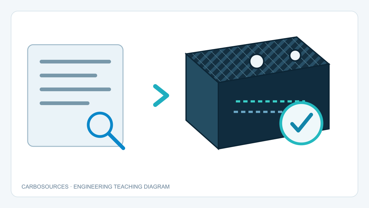
Start with the applied axial force, torque, bending, duty cycle and environment. Then define the tube and insert geometry, control the bond line and choose tests that expose the credible failure modes. This produces a joint specification that can be manufactured, inspected and improved with evidence rather than a connection based only on thread size and nominal bond area.