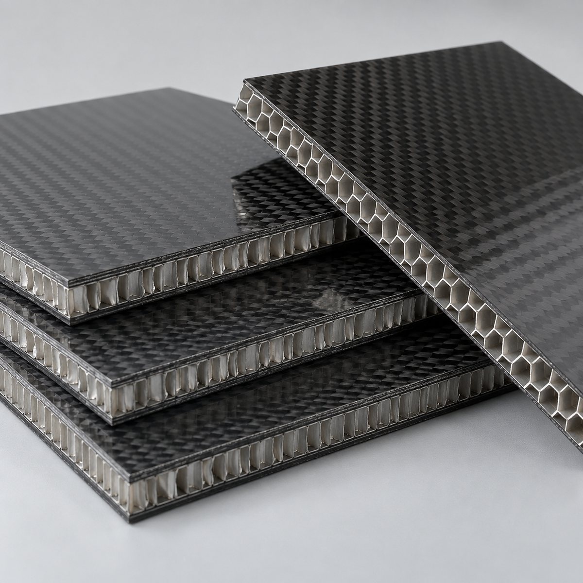
A carbon fiber sandwich panel is more than two carbon skins separated by a lightweight core. It is a structural system in which the face sheets, core, adhesive layer, edges and attachment points must transfer load together.
This matters because two carbon fiber sandwich panels with the same outside dimensions and total thickness can behave very differently. One may be controlled by face-sheet stress, another by core shear, and a third by a local insert that crushes the core long before the rest of the panel reaches its capacity.
Selecting a panel by thickness alone therefore misses the main engineering questions:
- How is the panel supported?
- Is the load distributed or concentrated?
- Which direction does the load follow?
- How much deflection is acceptable?
- Where do bolts, inserts or brackets introduce load?
- What temperature, moisture and impact conditions will the panel experience?
The useful starting point is the load path. Once that is understood, skin construction, core type, adhesive, edge details and inserts can be evaluated as parts of the same structure.
How a Carbon Fiber Sandwich Panel Carries Load
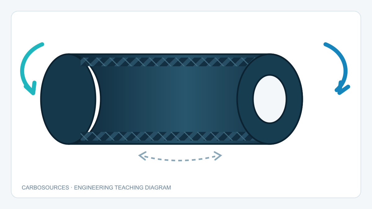
A sandwich panel behaves in some ways like an I-beam distributed across a surface. When the panel bends, one face sheet is mainly in tension and the opposite face sheet is mainly in compression. The core holds the skins apart and transfers shear between them.
Separating the skins increases the section depth, which can raise bending rigidity without filling the entire thickness with solid carbon laminate. This is the source of the familiar stiffness-to-mass advantage of sandwich construction. It does not mean that every thicker sandwich panel is automatically stronger or more suitable.
Each part has a different job:
| Panel element | Primary structural role | Typical design concerns |
|---|---|---|
| Carbon fiber face sheets | Carry tensile and compressive stresses caused by bending | Laminate direction, skin thickness, compression strength, surface damage |
| Lightweight core | Separates the skins and transfers transverse shear | Shear modulus, shear strength, compression strength, thickness and directionality |
| Skin-to-core adhesive | Transfers load between face sheets and core | Surface preparation, bond-line quality, peel stress, temperature and moisture |
| Edge closeout | Protects exposed core and transfers edge loads | Sealing, local reinforcement, machining and impact |
| Insert or hard point | Introduces concentrated mechanical loads | Pull-out, shear, torque, bearing, local crushing and alignment |
The carbon surface visible from the outside does not fully describe the structural skin. A cosmetic twill layer may sit over unidirectional or multiaxial reinforcement. The internal fiber directions determine how the skin responds to the actual load. The differences between woven and unidirectional reinforcement are explained in the plain weave, twill weave and unidirectional carbon fiber guide.
Why Bending Deflection and Core Shear Must Be Considered Separately
Panel deflection contains more than one component. For preliminary thinking, it is useful to separate total deflection into:
Total deflection = bending deflection + shear deflection
Bending deflection is strongly affected by the stiffness of the face sheets and the distance between them. Shear deflection depends more directly on the core shear modulus, core thickness, span and load arrangement.
This distinction explains why adding stiffer skins does not always solve a deflection problem. If a short panel with a soft core is governed by shear deformation, increasing face-sheet stiffness may produce only a limited improvement. Conversely, changing to a stronger core does not automatically solve a long-span panel governed by face-sheet bending or global buckling.
Boundary conditions also matter. A panel simply supported along two edges does not respond like the same panel clamped on four sides. A uniformly distributed pressure does not create the same stress field as a small foot, bolt or equipment mount carrying the same total force.
Before comparing panel constructions, define at least:
- clear unsupported span;
- support location and support width;
- point, line, distributed or edge load;
- load direction;
- allowable deflection;
- static, cyclic or impact loading;
- service temperature and moisture exposure.
Without these inputs, a statement such as “20 mm sandwich panel” describes geometry, not performance.
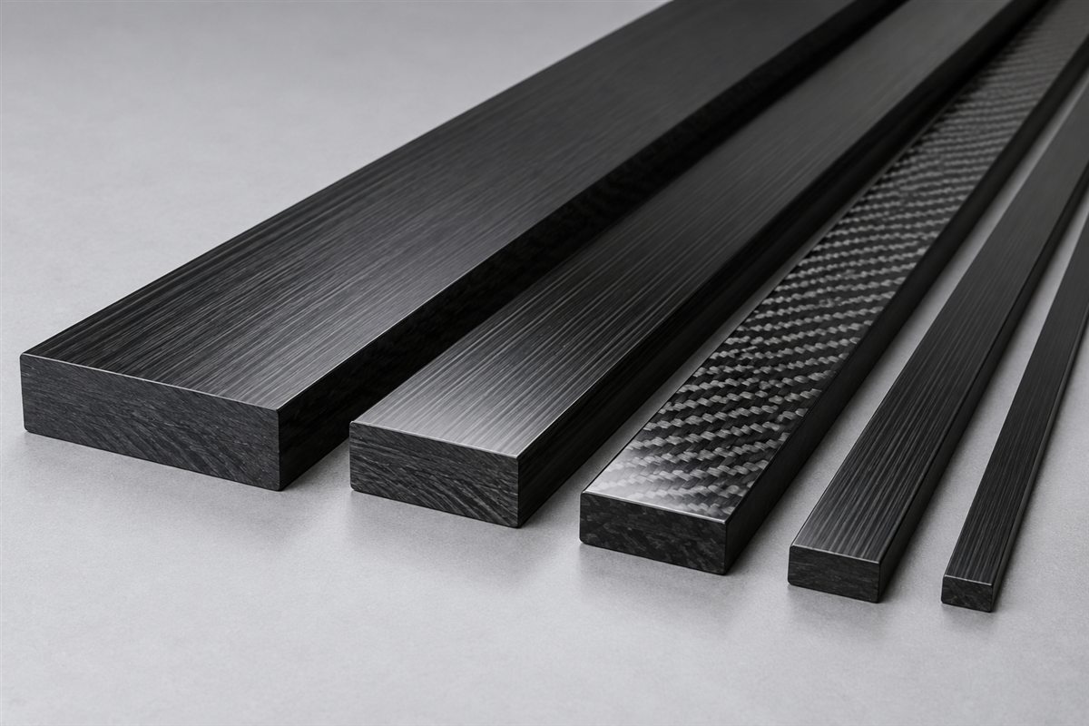
If the structure does not need a lightweight core, compare this approach with a solid laminate using the carbon fiber sheet thickness guide. A solid sheet and a sandwich panel can have the same outside dimensions while carrying load through very different mechanisms.
Core Shear Failure: When the Core Becomes the Weak Link
Core shear failure occurs when the shear stress or shear deformation in the core exceeds what the core can sustain. In a foam core, the failure may develop as an internal shear crack or a crushed and distorted region. In a honeycomb core, cell walls may buckle, tear or shear, depending on core direction and the load case.
Core shear can control the design when:
- the core has low shear strength or shear modulus;
- the panel carries a high transverse load over a relatively short span;
- strong face sheets shift the weak point into the core;
- the panel has already suffered impact or local crushing;
- honeycomb ribbon direction is not aligned with the intended structural direction;
- a cutout, edge or insert interrupts the normal load path.
Shear strength and shear modulus answer different questions. Strength relates to when the core fails. Modulus describes how much it deforms before that point. A core may meet a strength requirement while still allowing more deflection than the application permits.
Honeycomb properties are commonly directional. The ribbon direction and transverse direction can have different shear values, so a drawing should identify cell orientation when it affects performance. “Aluminum honeycomb” or “aramid honeycomb” alone is not a complete core definition.
The engineer should also distinguish core shear failure from shear crimping. Core shear failure refers broadly to the core material reaching its shear limit. Shear crimping is an instability mode in which insufficient core shear stiffness allows the faces to move and buckle together locally under in-plane compression. They may look related in a damaged part, but their design checks are not identical.
Face Sheet Wrinkling: A Local Compression Instability
Face sheet wrinkling occurs when the compressed skin locally buckles into or away from the supporting core. It is a local instability, not the same as the entire panel bowing in global buckling.
Wrinkling resistance depends on the interaction of the face sheet and core. Relevant variables include:
- face-sheet compressive and flexural properties;
- skin thickness and laminate quality;
- core compressive modulus;
- core shear modulus;
- bond quality between skin and core;
- initial waviness or manufacturing defects;
- temperature and environmental conditioning;
- impact damage or an existing disbond.
A thin high-modulus skin can still wrinkle if the core does not provide adequate local support. Increasing core thickness may improve overall panel bending rigidity, but core thickness alone does not guarantee greater wrinkling resistance. The core material properties and face-to-core bond remain part of the calculation.
With honeycomb, another local instability can occur: intracell buckling or dimpling. Instead of forming a broader wrinkle, a very thin skin can deflect between individual honeycomb cell walls. Cell size, skin thickness and face-sheet stiffness influence this mode. This is one reason a large-cell honeycomb should not automatically be paired with an extremely thin face sheet.
The practical distinction is:
- Face wrinkling: local wave-like instability of the compressed skin supported by the core.
- Intracell buckling or dimpling: local skin deformation between honeycomb cell walls.
- Global buckling: instability of the complete panel over its overall length or width.
- Face compression failure: the laminate itself reaches its compressive limit without wrinkling being the controlling mechanism.
Other Composite Sandwich Panel Failure Modes
Core shear and face wrinkling are only two possible limits. A useful design review considers all credible modes and identifies which one is expected to occur first.
Face-sheet tensile or compressive failure
The skins may reach their material limit before the core fails. The result depends on the full laminate, not only the surface weave. Fiber direction, ply balance, holes, notches and local load introduction all influence the available strength.
Skin-to-core debonding
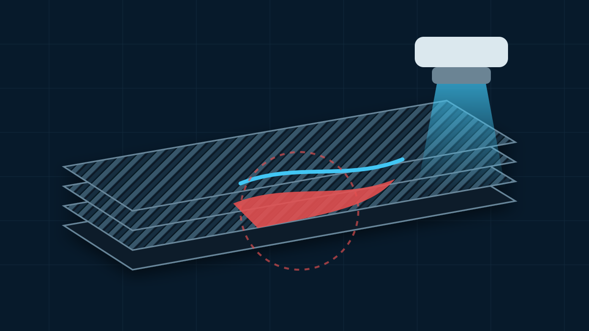
If the adhesive interface cannot transfer load, the skin and core begin to act as separate parts. Debonding may originate from poor surface preparation, inadequate adhesive coverage, peel stress, impact damage, moisture, temperature exposure or a poorly detailed edge. Even a small disbond can change the local stress field and allow further growth under cyclic loading.
Core crushing and indentation
A concentrated load can compress the core beneath a bolt head, foot, clamp or roller. The skin may remain visually intact while the core below it has already lost thickness or stiffness. Load-spreading plates, hard points or locally reinforced regions are often needed where concentrated compression enters the panel.
Global panel buckling
An edge-loaded panel may lose stability as a complete structure. Panel dimensions, edge restraint, bending stiffness and core shear stiffness all affect this mode. A coupon material property cannot, by itself, predict global buckling of the finished panel.
Edge and cutout failure
Cut edges can expose the core and interrupt the face-to-core bond. Holes and openings produce stress concentrations, and a fastener placed too close to an unsupported edge may split the closeout or peel a skin away from the core. The machining drawing should therefore treat edge construction as part of the structure.
Impact damage
Impact can dent a skin, crush the core or create a hidden disbond. Visible surface damage does not always show the full internal damage area. Applications exposed to dropped tools, debris or repeated handling may require impact criteria and an inspection method in addition to static strength checks.
Honeycomb Core vs Foam Core: Choose by Failure Mode
The question is not whether honeycomb or foam is universally better. The better core is the one whose properties, manufacturing behavior and environmental limits fit the controlling load cases.
| Design consideration | Honeycomb core | Structural foam core |
|---|---|---|
| Internal structure | Discrete cells with directional properties | Continuous cellular material; degree of isotropy depends on grade |
| Local skin support | Depends on cell size and wall geometry | Continuous support across the skin |
| Shear direction | Ribbon and transverse directions may differ | Often less directional, but datasheet values still need review |
| Machining and shaping | Cut cells require closeouts or potting | Often easier to contour or locally machine |
| Water management | Breached cells can provide a path for retained moisture | Closed-cell grades may limit uptake, but cut surfaces and damage still require attention |
| Inserts | Commonly use potted regions, through inserts or hard points | Can use potted inserts or local high-density core replacement |
| Local damage | Cell collapse, skin dimpling and bond damage are possible | Crushing, indentation, shear cracking and wrinkling are possible |
Within a core family, a higher-density grade commonly provides greater compression and shear capability, but it also adds mass. Density is not a substitute for the manufacturer’s directional mechanical data or project-specific testing.
Temperature is equally important. The core, resin and adhesive must remain compatible through manufacturing and service. A core that performs well at room temperature may not be appropriate near a heat source or through repeated thermal cycles. Moisture, chemicals, flammability and smoke requirements may further narrow the choice.
For many projects, core selection becomes clearer after answering three questions:
1. Is the panel governed by distributed bending, concentrated compression or in-plane load? 2. Does the geometry require extensive contouring, pockets, inserts or sealed edges? 3. Which environmental condition is most likely to reduce bond or core performance?
Why Sandwich Panel Inserts Need Their Own Load Path
Lightweight cores are efficient when loads are distributed, but a threaded fastener introduces force through a very small area. A standard screw placed directly into a low-density core cannot be assumed to provide a durable structural connection.
An insert or hard point must spread load from the fastener into a larger region of the panel. Depending on the configuration, the load may pass through the insert body, potting compound, one or both skins, and the surrounding core.
Common approaches include:
- Potted blind insert: an insert bonded into an enlarged cavity, typically accessed from one face.
- Through insert: a load path extending through the panel thickness, often useful when both faces are accessible.
- Local high-density core: a stronger core block replaces the lightweight core around the attachment.
- Solid laminate hard point: local solid composite provides bearing and through-thickness support.
- Bonded backing plate: a plate spreads load over a wider area of one face.
- Edge member or closeout: a structural perimeter element carries fasteners near the edge.
These are categories, not interchangeable solutions. A suitable detail depends on the load direction, available access, skin construction, panel thickness and service environment.
Insert Loads That Must Be Defined
The phrase “M6 insert” describes a thread, not a structural requirement. At minimum, determine which of the following loads apply:
Pull-out
Pull-out acts normal to the panel and attempts to extract the insert. The design must resist failure of the threads, insert-to-potting bond, potting-to-core interface, local skin and surrounding core.
Push-through
A compressive load may push the insert or fastener head through the panel. Core compression and the area supported by the face sheets become important.
In-plane shear
Shear acts parallel to the panel surface. Clearance, insert fit, local bearing and the connection between the hard point and both skins influence movement and strength.
Installation and service torque
Tightening torque can rotate an inadequately bonded insert or crush the panel beneath a washer or bracket. Installation torque and operating torque should be specified separately from axial load.
Bending moment and peel
An offset bracket can apply a moment even if the nominal force appears to be simple tension or shear. This can concentrate peel stress in one face sheet or at the edge of the potted region.
Cyclic loading
Repeated loads may grow small disbonds, loosen interfaces or damage the core at stresses below a one-time static failure load. Duty cycle and expected number of load events therefore belong in the design input.
What Controls a Potted Insert Design?
The size of the visible threaded insert is only one variable. The surrounding load-spreading feature often controls the result.
Important parameters include:
- potting diameter and depth;
- whether potting reaches one or both skins;
- insert body geometry and anti-rotation features;
- core type, density and thickness;
- face-sheet laminate and thickness;
- distance to panel edges, cutouts and adjacent inserts;
- bond-line preparation and cure;
- fastener preload and washer or bracket footprint;
- insert material and corrosion isolation;
- drilling and installation tolerances.
Making the potted region larger may distribute load over more area, but it also increases weight and can create a stiff local discontinuity. Making it too small may overload the core, potting interface or skin. The correct size comes from the load case and construction, followed by validation where required.
Metal compatibility also deserves attention. Carbon fiber is electrically conductive. If an aluminum insert contacts exposed carbon in the presence of moisture or another electrolyte, galvanic corrosion can attack the aluminum. Isolation layers, coatings, sealed interfaces or a different insert material may be required. The complete material stack should be defined rather than assuming that adhesive alone provides permanent isolation.
Manufacturing Details That Affect Structural Behavior
Good analytical inputs cannot compensate for an uncontrolled manufacturing process. Several details can change how the finished panel carries load.
The selected production route also affects laminate consolidation, surface finish, tooling and practical geometry. The custom carbon fiber manufacturing process guide provides a broader comparison of common process choices.
Skin balance and cure
Asymmetric skins, resin content differences or mismatched cure shrinkage can contribute to warpage. Cosmetic requirements should be separated from structural laminate requirements, while still controlling both faces as part of one panel.
Core preparation
Core thickness, surface condition, cell direction and local repairs need control. Gaps, crushed cells or contamination can interrupt load transfer.
Adhesive coverage
The adhesive must create a continuous load path without excessive voids or starved regions. The appropriate film, paste or other bonding process depends on the selected skin and core system.
Machining and edge closeouts
Cutting a finished panel can expose cells, foam and bond lines. CNC features should be planned with the closeout and insert strategy rather than added as a final operation. The carbon fiber CNC machining service explains the drawing inputs used for machined composite components.
Insert location and alignment
An insert that is structurally adequate but tilted, off-position or proud of the surface can still make the assembly unusable. Datum references, positional tolerance, perpendicularity and final thread inspection should be stated on the drawing.
How to Validate a Carbon Fiber Sandwich Panel
Validation should match the expected failure mode. One generic coupon cannot confirm every aspect of a finished panel.
Possible checks include:
- overall dimensions and total thickness;
- flatness where functionally required;
- face-sheet and edge visual inspection;
- insert position, height and perpendicularity;
- thread gauge inspection;
- tap torque or installation torque check;
- insert pull-out, push-through or in-plane shear test;
- panel flexural test under a representative span;
- core shear or flatwise compression characterization;
- environmental conditioning before mechanical testing;
- proof loading of a representative assembly;
- non-destructive inspection when justified by construction and risk.
Test fixtures matter. A pull-out result changes with support-ring diameter, fixture stiffness and load alignment. A panel bending result changes with span and support condition. Reports should therefore record the specimen construction, conditioning, fixture and observed failure mode rather than publishing a single force value without context.
The failed specimen also contains useful information. Thread failure, insert rotation, potting fracture, skin delamination, core shear and skin-to-core debonding point to different design changes.
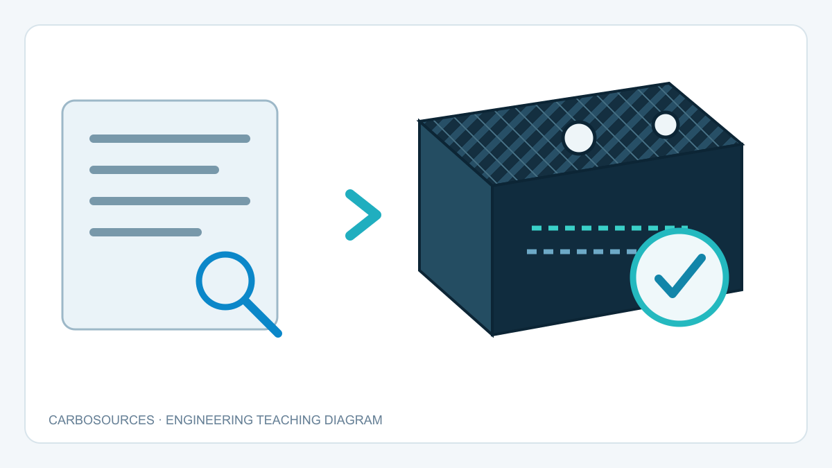
What to Specify Before Ordering Carbon Fiber Sandwich Panels
A useful drawing and request package separates required performance from preferences.
Panel geometry
- finished length, width and total thickness;
- corner radii, cutouts, slots and pockets;
- unsupported span and support locations;
- critical datums, flatness and dimensional tolerances.
Face sheets
- structural requirement or approved laminate definition;
- skin thickness where controlled;
- principal load direction;
- visible face or faces;
- weave alignment, gloss or matte finish and protection requirements.
Core
- preferred core family and reason for the preference;
- core thickness and density or required properties;
- honeycomb cell size and orientation where applicable;
- temperature, moisture, chemical and fire requirements.
Edges and machining
- open, sealed, capped, potted or structurally closed edges;
- final CNC profile and hole locations;
- areas that need local reinforcement;
- downstream machining or assembly operations.
Inserts and interfaces
- thread type and engagement;
- insert material;
- pull-out, push-through, shear, torque and moment loads;
- bracket or washer contact area;
- repeated assembly requirements;
- positional and angular tolerances;
- corrosion-isolation requirements.
Acceptance
- functional dimensions and cosmetic surfaces;
- inspection records required;
- prototype or first-article testing;
- proof-load or destructive test requirements;
- packaging and surface protection.
For an early design, load, span, target mass and allowable deflection are more useful than an unverified laminate schedule. For a released design, supply the controlled drawing revision and material notes. The existing custom carbon fiber sandwich panel page provides a broader overview of panel, edge and machining inputs.
Frequently Asked Questions
Is a thicker carbon fiber sandwich panel always stronger?
No. Increasing the distance between skins can improve bending rigidity, but the controlling limit may still be core shear, face wrinkling, global buckling, local crushing, debonding or an attachment detail. Total thickness must be evaluated together with skin construction, core properties, span and load introduction.
What is the difference between core shear failure and face sheet wrinkling?
Core shear failure occurs within the core when shear stress or deformation exceeds its capability. Face sheet wrinkling is a local instability of the compressed skin supported by the core. They involve different material properties and may require different design changes.
Is honeycomb core better than foam core?
Neither is universally better. Honeycomb can provide highly efficient structures but has directional properties and requires attention to cell orientation, cut edges and inserts. Structural foam provides continuous skin support and can simplify shaping, but foam grade, density, temperature capability and shear performance still require review.
Can a threaded insert be installed directly into the core?
A low-density core should not be treated like a solid block. Structural inserts normally require a designed load-spreading feature such as potting, a high-density core block, a solid laminate hard point, a through insert or a backing plate.
Can holes be added after a sandwich panel is manufactured?
They can be machined when the panel construction and edge treatment support the feature. Drilling may expose the core or interrupt a bond line, so the final hole, sealing, hard-point and tolerance requirements should be included in the machining plan.
Which test proves that an insert is safe?
No single test covers every load state. Pull-out, push-through, in-plane shear, torque, cyclic loading and environmental exposure examine different risks. The test method should reproduce the relevant support and load path as closely as practical.
Final Design Principle
Reliable carbon fiber sandwich panels are designed from the expected failure modes, not from thickness alone. The face sheets, core, adhesive, edges and inserts must form a continuous load path.
Start with span, support, load direction, allowable deflection and attachment details. Then select the skin, core and local reinforcement that address the governing modes. This approach produces a clearer specification and makes prototype testing more meaningful because each test is connected to a defined structural question.