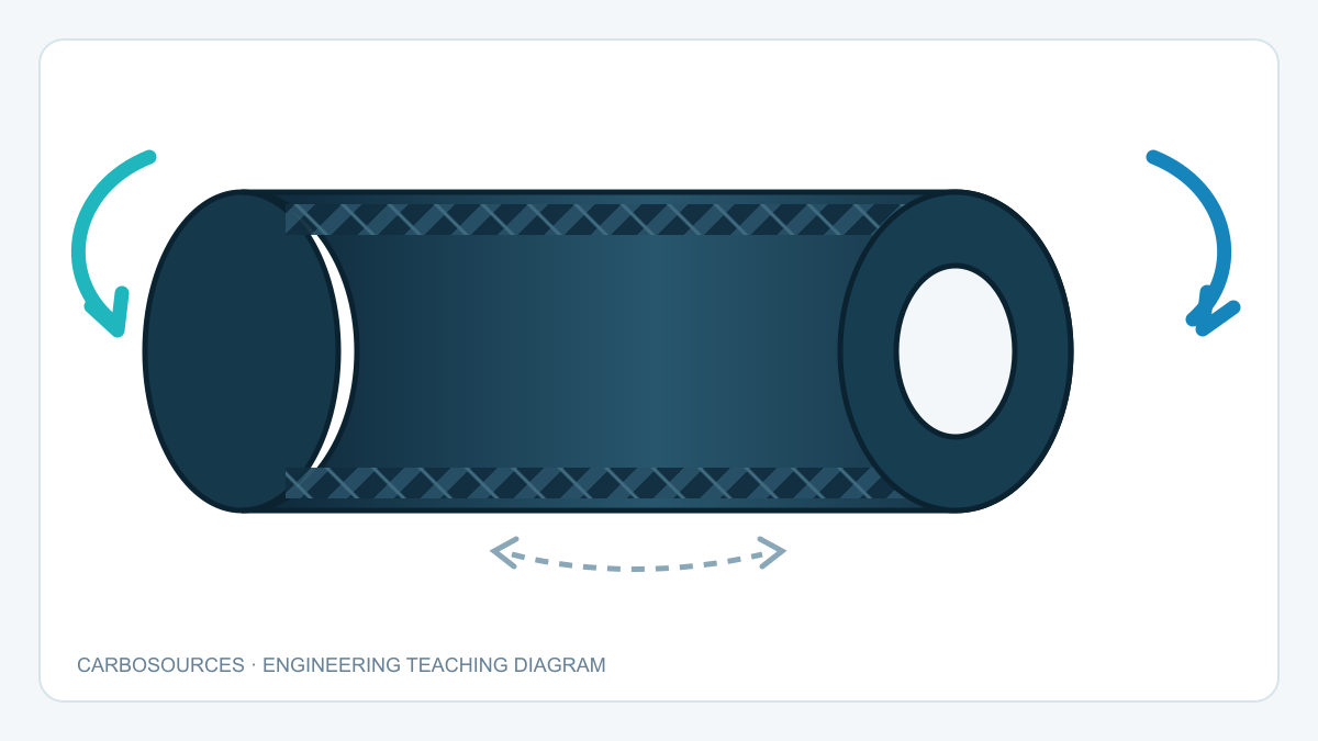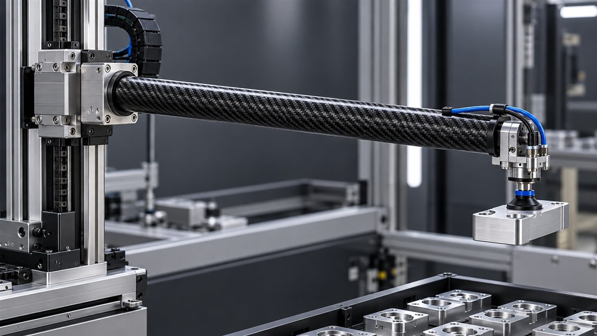
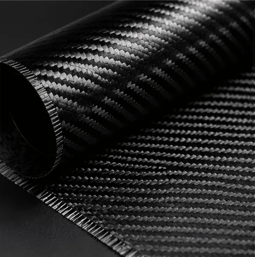
A carbon fiber cover, a flat mounting plate and a hollow tube can all be described as “custom carbon fiber parts.” They do not necessarily belong on the same production line. Their shapes, load paths, visible surfaces and required quantities create different tooling and layup problems.
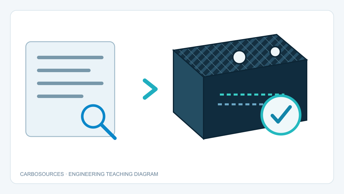
That is why choosing among carbon fiber manufacturing methods for custom parts should start with the part specification, not a process name. A drawing and a short description of how the component will be used give a manufacturer a better basis for recommending materials, tooling, forming and finishing steps.
Start with the job the part must do
Define the part’s function before comparing manufacturing routes. An enclosure cover may be judged mainly by fit, surface appearance and weight. A bracket or machine component may also need defined stiffness, load capacity, hole locations and a repeatable interface with another part. A tube used as a beam raises questions about bending, torsion, end connections and local reinforcement.
“Strong and lightweight” is too broad to select a laminate. Specify the direction and type of loading where known. If a part replaces a metal component, show the original part, its mounting arrangement and the reason for changing material. The design may need to change rather than simply copying the metal geometry in carbon fiber.
For background on how fiber arrangement affects a laminate, see our guides to plain, twill and unidirectional carbon fiber and 3K tow, weave and layup.
Compare the main process routes
The table below is a selection guide, not a performance guarantee. Part design, resin system, tooling and process control affect the result within every route.
| Route | How it works | Points to evaluate for a custom part |
|---|---|---|
| Wet layup | Dry reinforcement is placed in a mold and wetted with resin by hand. | Tooling approach, operator access, laminate consistency, visible surface and finishing effort. |
| Wet layup with vacuum bagging | The wet laminate is bagged and compacted during cure. | Bag access, corner bridging, resin bleed, finish requirements and process repeatability. |
| Resin infusion | Dry reinforcement is bagged first; vacuum draws resin through the stack. | Leak-tight tooling, resin flow paths, dry spots, part size and suitable production setup. |
| Prepreg layup | Reinforcement arrives with a controlled resin content and follows its specified storage and cure schedule. | Cure equipment, tooling temperature capability, material handling and required laminate quality. |
| Matched-tool or compression molding | Material is formed between controlled tool surfaces under pressure. | Tool investment, geometry, surface requirements and the planned production quantity. |
Vacuum bagging and resin infusion are often confused. In vacuum-bagged wet layup, the fiber has already been wetted before the bag is sealed. In infusion, the fiber is dry when the bag is sealed, and resin enters afterward. Vacuum bagging is therefore a step that can be used in different manufacturing routes, not a synonym for infusion.
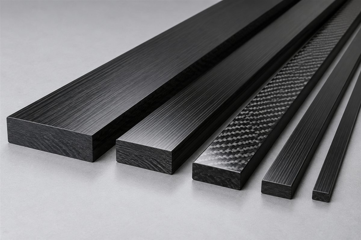
No route should be selected from this table alone. A contoured shell may raise different questions from a straight tube or a CNC-cut plate. For parts made from stock laminates, the main manufacturing work may involve material selection, cutting, machining and edge finishing rather than molding a new shape. Our carbon fiber sheet thickness guide discusses one of those decisions.
Let geometry and finish narrow the options
Mark every surface that matters on the drawing. A cosmetic outer face, a bonding face and an unseen inner face may require different treatment. Deep corners and tight radii can make it difficult for fabric and bagging materials to sit against the mold without bridging. Holes, slots, inserts and trimmed edges also need to be considered before tooling is finalized.
For a machined plate, state which edges and holes locate other components. For a tube, identify the critical inside or outside diameter, end condition and any bonded or threaded connection. Our carbon fiber tube tolerance guide explains why the controlled dimension should be named explicitly.
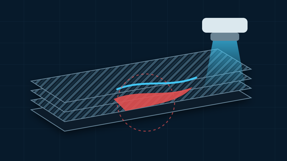
Avoid asking for a blanket tolerance on every feature if only a few interfaces control assembly. Mark critical dimensions separately and explain how the part will be checked. That lets the supplier discuss a realistic inspection plan alongside the proposed process.
Include quantity and development stage
A prototype and a repeat production part may justify different tooling decisions. The relevant quantity is not only the first order: include the expected annual demand, likely design revisions and whether a prototype must use the eventual production process.
The lowest tooling cost does not always give the lowest cost per accepted part. Mold construction, cycle time, material waste, machining, finishing and inspection all contribute. Conversely, expensive production tooling may be difficult to justify while geometry is still changing. Treat any cost comparison as project-specific until a supplier has reviewed the drawing and acceptance criteria.
Prepare a useful manufacturing brief
Before asking a manufacturer to recommend a process, provide:
- A dimensioned 2D drawing and, where available, a 3D model with revision number.
- The intended application, mounting method and known load directions.
- Critical fit dimensions, hole positions and inspection requirements.
- Required appearance, including which face is visible and the preferred finish.
- Target weight or stiffness, if these are measured requirements rather than preferences.
- Prototype quantity, expected repeat quantity and anticipated design changes.
- Any temperature, chemical, UV or electrical environment relevant to material selection.
These inputs do not require the buyer to prescribe every fiber orientation or cure parameter. They help the engineering team identify the constraints that the process must satisfy. Carbosources’ custom carbon fiber parts and CNC machined parts pages show the types of drawing-based work that can be discussed alongside this guide.
A practical selection rule
Describe function, geometry, interfaces, finish, quantity and acceptance criteria first. Compare wet layup, vacuum bagging, infusion, prepreg or molded routes only after those requirements are clear. The most useful answer is not a universal “best process”; it is a documented process proposal tied to the actual part.